. 2024 Jul 9;15(8):4498-4512.
doi: 10.1364/BOE.524013. eCollection 2024 Aug 1.

Adaptive optics in an oblique plane microscope

Affiliations

Adaptive optics in an oblique plane microscope

Conor Mcfadden et al. Biomed Opt Express. .

Abstract

Adaptive optics (AO) can restore diffraction-limited performance when imaging beyond superficial cell layers in vivo and in vitro, and as such, is of interest for advanced 3D microscopy methods such as light-sheet fluorescence microscopy (LSFM). In a typical LSFM system, the illumination and detection paths are separate and subject to different optical aberrations. To achieve optimal microscope performance, it is necessary to sense and correct these aberrations in both light paths, resulting in a complex microscope system. Here, we show that in an oblique plane microscope (OPM), a type of LSFM with a single primary objective lens, the same deformable mirror can correct both illumination and fluorescence detection. Besides reducing the complexity, we show that AO in OPM also restores the relative alignment of the light-sheet and focal plane, and that a projection imaging mode can stabilize and improve the wavefront correction in a sensorless AO format. We demonstrate OPM with AO on fluorescent nanospheres and by imaging the vasculature and cancer cells in zebrafish embryos embedded in a glass capillary, restoring diffraction limited resolution and improving the signal strength twofold.


Conflict of interest statement

The authors declare no conflict of interest.

Figures
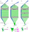
Fig. 1.
Fig. 1.
Adaptive optics in an Oblique Plane Microscope (OPM). A. Creation of an oblique plane light-sheet (blue) and collection of fluorescence (green) in an aberration free case. The overall point spread function (PSF, pink) is the product of the excitation (blue) and detection PSF (green), shown below. B. Imaging in the presence of aberrations: The oblique light-sheet has changed its location and angle due to refraction. Fluorescence emission occurs outside the focal plane, the wavefront is aberrated, and a distorted image is formed outside the image plane. The excitation does not overlap with the best focus of the detection PSF, resulting in a wider overall PSF, shown below. Autofocusing (AF) can re-center the light-sheet but will not undo the overall distortions of the detection PSF. C. A corrective optical element, labeled AO, compensates the aberrations of the fluorescence wavefront, restoring a diffraction limited image of the emitter. The same corrective element also imprints a phase correction onto the ingoing light-sheet, such that its distortion in sample space is compensated. The corrective element recovers the diffraction limited PSF of aberration free imaging, shown below.
Fig. 2.
Fig. 2.
Setup for Oblique Plane Microscopy with adaptive optics. A. Schematic overview of the setup. B. Rendering of a CAD model of the setup. The optical microscope is assembled on an elevated breadboard and the VAST BioImager system is shown in white and light gray to the left. C. Photograph of the experimental setup, corresponding to the boxed red region in B. PL: Powell lens, TL: Tube lens,SL: Scan lens, L: Achromatic doublet lens, O: Objective.
Fig. 3.
Fig. 3.
Illustration of the multi-angle projection method. A. Schematic illustration of a sample, the primary objective and a light-sheet (shown in blue). A focal sweep (violet arrow) is obtained by rapidly scanning the light-sheet and the corresponding focal plane so that they span the light-blue shaded volume. The dashed lines show three individual positions, labeled 1-3, along the focal sweep. B. When the focal sweep occurs during one camera exposure, a projection is formed (right). Adding additional shear (red arrow) during the focal sweep changes the viewing direction of the projection. Panels 1-3 show instantaneous images along the focal sweep, corresponding to the dashed lines in A. The added shear in this illustration results in a top-down view, with the viewing direction indicated with an arrow in A.
Fig. 4.
Fig. 4.
Adaptive optics on fluorescent nanospheres embedded in a glass capillary with agarose. Maximum intensity projections of 3D stacks of nanospheres are shown A. without and B. with AO-correction. Inlays: logarithm of the power spectral density of the x-y images. C. Zernike coefficients for the measured AO-correction, along with the wavefront (inlay). Zernike coefficient abbreviations: ASM: Astigmatism, TRE: Trefoil, Tetra: Tetrafoil, Penta: Pentafoil, Vert: Vertical, Oblq: Oblique.
Fig. 5.
Fig. 5.
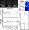
Performance of iterative adaptive optics with static and projection imaging using fluorescent nanospheres embedded with Agarose in a glass capillary. A. Fluorescent nanospheres, as imaged with system, static AO, and projection AO correction, respectively. Maximum intensity projections of 3D stacks are shown. B. Overall Zernike coefficient amplitudes for 20 different measurements along the capillary length using static and projection AO, displayed as box plots. C. Mean (left) and standard deviations (right) of all wavefronts measured using (top) static AO and (bottom) projection AO. D. Focus correction required for either the uncorrected case or post-AO correction to reach the highest DCTS image quality. E Peak bead intensity for all measurements and AO conditions. Zernike coefficient abbreviations: ASM: Astigmatism, TRE: Trefoil, Tetra: Tetrafoil, Penta: Pentafoil. Vert: Vertical, Oblq: Oblique. For statistical testing, alternate hypotheses were (for example) D: H1 = |Proj| < |Stat| and E: H1 = Proj > Stat. A one-sided Mann-Whitney U test was used for all calculations. Significance is notated as *: p < 0.05, **: p < 0.01, ***: p < 0.001. Mean values are represented by green triangles in D-E.
Fig. 6.
Fig. 6.
Projection based adaptive optics in a zebrafish larva, labelled with the vasculature marker Tg(kdrl:EGFP). A. Maximum intensity projections (MIPs) of a stack acquired with the system correction applied to the mirror, and after performing the autofocusing routine. B. MIPs of a stack acquired after projection AO correction. C. The wavefront correction applied in B. D. List of the corresponding Zernike coefficients. Zernike coefficient abbreviations: ASM: Astigmatism, TRE: Trefoil, Tetra: Tetrafoil, Penta: Pentafoil.Vert: Vertical, Oblq: Oblique.
Fig. 7.
Fig. 7.
Projection AO for subcellular imaging of cancer metastasis in zebrafish xenografts. The xenografted zebrafish was mounted in agarose in a glass capillary, and the CHT region was imaged. A. Uncorrected XY, XZ and YZ MIPs of vasculature Tg(kdrl:eGFP) (cyan) and A375 cancer cells labelled with the actin marker pLVX-iNeo-mRuby-Tractin (magenta). B. Projection AO-corrected stacks, with the measured wavefront show in the inlay (color bar is the wavefront error in µm). C. Zoomed-in regions (ROI designated in A) for the vasculature and D. cancer cells emphasize the improvement in fine details after AO correction. Note that D roughly shows the ROI on which projection-AO was performed.

Update of

References

    1. Stelzer E. H. K., Strobl F., Chang B.-J., et al. , “Light sheet fluorescence microscopy,” Nat. Rev. Methods Primers 1(1), 73 (2021).10.1038/s43586-021-00069-4 - DOI
    1. Davies R., Kasper M., “Adaptive optics for astronomy,” Annu. Rev. Astron. Astrophys. 50(1), 305–351 (2012).10.1146/annurev-astro-081811-125447 - DOI
    1. Booth M. J., “Adaptive optics in microscopy,” Philosophical Transactions of the Royal Society A: Mathematical, Physical and Engineering Sciences 365, 2829–2843 (2007). - PubMed
    1. Hampson K. M., Turcotte Raphaël, Miller D. T., et al. , “Adaptive optics for high-resolution imaging,” Nat. Rev. Methods Primers 1(1), 68 (2021).10.1038/s43586-021-00066-7 - DOI - PMC - PubMed
    1. Débarre D., Botcherby E. J., Watanabe T., et al. , “Image-based adaptive optics for two-photon microscopy,” Opt. Lett. 34(16), 2495–2497 (2009).10.1364/OL.34.002495 - DOI - PMC - PubMed

LinkOut - more resources