. 2024 Oct 1;15(1):8511.
doi: 10.1038/s41467-024-52860-y.

Molecular architecture and functional dynamics of the pre-incision complex in nucleotide excision repair

Affiliations

Molecular architecture and functional dynamics of the pre-incision complex in nucleotide excision repair

Jina Yu et al. Nat Commun. .

Abstract

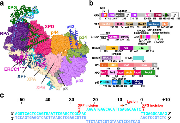
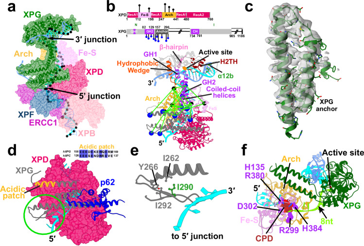
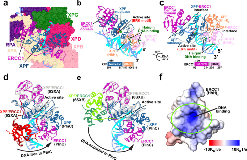
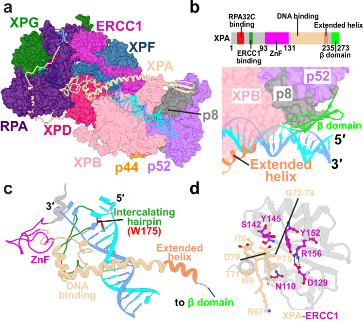
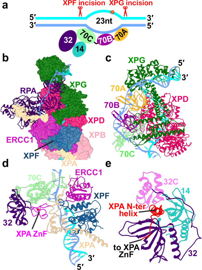
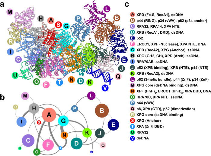
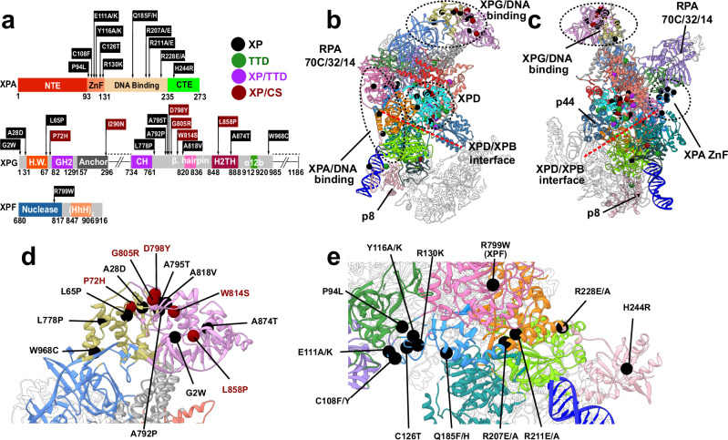
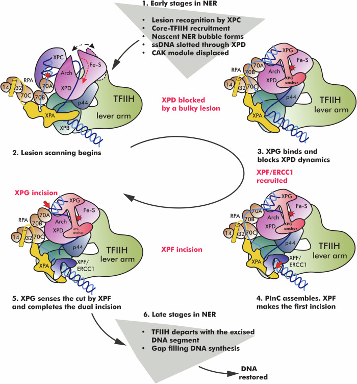
Nucleotide excision repair (NER) is vital for genome integrity. Yet, our understanding of the complex NER protein machinery remains incomplete. Combining cryo-EM and XL-MS data with AlphaFold2 predictions, we build an integrative model of the NER pre-incision complex(PInC). Here TFIIH serves as a molecular ruler, defining the DNA bubble size and precisely positioning the XPG and XPF nucleases for incision. Using simulations and graph theoretical analyses, we unveil PInC's assembly, global motions, and partitioning into dynamic communities. Remarkably, XPG caps XPD's DNA-binding groove and bridges both junctions of the DNA bubble, suggesting a novel coordination mechanism of PInC's dual incision. XPA rigging interlaces XPF/ERCC1 with RPA, XPD, XPB, and 5' ssDNA, exposing XPA's crucial role in licensing the XPF/ERCC1 incision. Mapping disease mutations onto our models reveals clustering into distinct mechanistic classes, elucidating xeroderma pigmentosum and Cockayne syndrome disease etiology.


Conflict of interest statement

The authors declare no competing interests.

Figures

Fig. 1
Fig. 1. Integrative model of the PInC unveils the overall structural organization of the assembly.
a View of the PInC assembly colored by subunits. XPG, XPF/ERCC1, p62, and DNA are shown in cartoon representation. TFIIH, XPA, and RPA are shown in surface representation. The lesion containing DNA strand is shown in cyan; the undamaged strand is shown in blue. b Domain organization of the PInC constituent proteins XPG, XPF, ERCC1, XPA, RPA, XPB, XPD, and p62 mapped onto their respective sequences. Abbreviations denote H.W.—hydrophobic wedge; GH—gateway helix; CH—coiled-coil helix; H2TH—helix-2-turn-helix; H.D.—helicase domain; HhH—helix-hairpin-helix; DRD—damage recognition domain; NTE—N-terminal extension. c Schematic showing the DNA substrate of PInC, the length of the NER bubble, and the positions of the lesion site (red star) and the two incision sites (red scissor symbols).
Fig. 2
Fig. 2. The XPG nuclease bridges the opposing ends of the NER bubble, providing an unexpected 5′ incision sensing mechanism.
a View of XPG at the 3′ DNA junction. XPG is depicted as cartoon and transparent surface and colored in dark green. The path of the DNA through TFIIH’s XPD subunit is shown by black spheres placed at the phosphorus atoms. b Crosslinks between XPG and XPD mapped onto the PInC structure. The XPD Arch and Fe-S domains are colored in orange and purple, respectively. XPG and XPD residues participating in the crosslinks are depicted as blue and black spheres, respectively. A schematic of the crosslinks mapped onto XPD’s and XPG’s sequences is shown above. Conserved structural motifs in the XPG catalytic core are shown; the two XPG coiled-coil helices are shown in purple; the XPG anchor domain is shown in gray. c The XPG anchor domain fitted into a segment from the TFIIH/XPA/DNA cryo-EM density (EMDB accession code: EMD–4970). d Overlay of AlphaFold2 docking models of the XPG-anchor and the p62 XPD-anchor with XPD. The β-hairpin, packed against the XPG-anchor domain is highlighted by a green circle. The acidic patch of XPG is highlighted in orange. The inset displays the sequence alignment of the acidic patches of human XPG and XPC. e Zoomed-in view of the β-hairpin interacting with the XPD anchor and ssDNA at the 5′ junction. A hydrophobic cluster involving residue I290 colored in green. I290N substitution is a recognized XP/CS disease mutant. f A CPD lesion blocked inside XPD’s DNA-binding groove near His135 and 8 nucleotides away from the 3′ junction.
Fig. 3
Fig. 3. XPF/ERCC1 is positioned for precise incision at the 5′ DNA junction.
a View of XPF/ERCC1 at the 5′ junction. ERCC1 and XPF are depicted in cartoon representation and colored in magenta and dark blue, respectively. The damaged and undamaged DNA strands are shown in cyan and light blue, respectively. b View of the XPF/ERCC1 heterodimer interacting with DNA at 5′ junction. The ERK active site motif in shown explicitly and colored in red. XPF and ERCC1 are colored by domain. A schematic representation of the XPF and ERCC1 sequences, indicating the domains, is shown below. c View of the XPF/ERCC1 heterodimer rotated by 70° around the dsDNA axis. d Conformational shift of XPF/ERCC1 relative to the DNA-free XPF/ERCC1 structure (6SXA). e Conformational shift of XPF/ERCC1 relative to the DNA-engaged XPF/ERCC1 structure (6SXB). The XPF nuclease and ERCC1 central domains are overlayed for comparison. The XPF/ERCC1 (HhH)2 domains are colored in red and dark red in the DNA-free structure and green and dark green in the DNA-engaged structure. ERCC1 and XPF in the PInC are colored in magenta and blue, respectively. f Electrostatics of the ERCC1 (HhH)2 DNA-binding surface. The electrostatic potential is mapped onto the molecular surface and colored from red (negative) to blue (positive).
Fig. 4
Fig. 4. XPA rigging interlaces XPF/ERCC1 with DNA, XPD, XPB, and RPA at the 5′ junction and is key for licensing the XPF incision.
a View of XPA within the PInC assembly. XPA is depicted in cartoon representations and colored in tan. b Zoomed-in view highlighting of the interface of XPA’s β-domain and p8. TFIIH’s p8, p52, and XPB subunits are shown in surface representation. A schematic of XPA’s sequence colored by domain is shown above. c XPA interacting with DNA at the 5′ junction. XPA is colored by domains. The intercalating hairpin is shown in green and labeled. d Detailed residue interactions between the glycine-rich loop of XPA and the V-shaped groove of ERCC1. Residues are depicted in ball and stick representation and colored in purple and magenta.
Fig. 5
Fig. 5. RPA binds and protects the undamaged strand, engaging ssDNA with its 70A, 70B and 70C domains.
a Schematic representation of RPA’s DNA-binding core with the ssDNA of the undamaged strand. The ssDNA is engaged by three OB-fold domains (70A-70B-70C). b View of RPA within the PInC assembly. RPA is shown in cartoon representation and colored in purple. c View of RPA70AB situated near the 3′ junction and interacting with XPG and XPD. RPA70AB is colored by domains. d View of the RPA trimer core engaging ssDNA at the 5′ junction. The XPA zinc finger is wedged between RPA70C and 32D. e A view of XPA’s N-terminal XPA lodged between the RPA32C and RPA14 domains.
Fig. 6
Fig. 6. Network of dynamic communities underlie PInC’s functional dynamics.
a Communities identified from dynamic network analysis that transcend subunit divisions. b Graph of allosteric communication among communities. Nodes are sized by the number of residues in each community. Edge thickness represents the magnitude of dynamic communication between communities (betweenness). c Labels identifying the domains or structural elements participating in each dynamic community.
Fig. 7
Fig. 7. Human disease mutations mapped onto the PInC model are shown to localize at key community interfaces.
a Missense disease mutations mapped onto the sequences of XPG, XPA, and XPF. Disease phenotypes are labeled as XP, XP/CS, TTD, and XP/TTD and identified by symbols and color. b Map of human disease mutations (spheres) onto the PInC structure (anterior view) shown in cartoon representation and colored by community. The three primary clusters of mutations associated with XPG, TFIIH, and XPA are outlined with black dashed lines. c Map of human disease mutations onto the PInC structure shown in posterior view. d Close-up view of mutations within XPG. e Close-up view of mutations within XPA and XPF.
Fig. 8
Fig. 8. NER protein machinery undergoes a dramatic structural reorganization from lesion recognition to lesion scanning and strand incision.
The schematic represent key steps in the NER pathway—XPC lesion recognition, NER bubble extension, XPD-mediated lesion scanning, PInC assembly and dual incision of the damaged DNA segment, gap-filling synthesis, and DNA restoration. Core NER factors are shown in cartoon representation and color-coded. The position of the lesion is indicated by a red star. Red dashed arrows show the direction of ssDNA movement during the different stages of NER. White dotted arrow denotes the opening/closing dynamics of XPB during bubble expansion. Black dotted arrow denotes the opening/closing dynamics of XPD during lesion scanning. A red cross denotes the blocking of a lesion inside XPD and damage verification. Red arrows indicate the incision points on DNA by XPF/ERCC1 and XPG, respectively.

References

    1. Scharer, O. D. Nucleotide excision repair in eukaryotes. Cold Spring Harb. Perspect. Biol.5, a012609 (2013). - PMC - PubMed
    1. Wang, W., Xu, J., Chong, J. & Wang, D. Structural basis of DNA lesion recognition for eukaryotic transcription-coupled nucleotide excision repair. DNA Repair71, 43–55 (2018). - PMC - PubMed
    1. Brueckner, F., Hennecke, U., Carell, T. & Cramer, P. CPD damage recognition by transcribing RNA polymerase II. Science315, 859–862 (2007). - PubMed
    1. Marteijn, J. A., Lans, H., Vermeulen, W. & Hoeijmakers, J. H. Understanding nucleotide excision repair and its roles in cancer and ageing. Nat. Rev. Mol. Cell Biol.15, 465–481 (2014). - PubMed
    1. D’Souza, A., Blee, A. M. & Chazin, W. J. Mechanism of action of nucleotide excision repair machinery. Biochem. Soc. Trans.50, 375–386 (2022). - PMC - PubMed

Publication types

MeSH terms