

Mechanical analysis of modified femoral neck system in the treatment of osteoporotic femoral neck fractures
- PMID: 39367368
- PMCID: PMC11452960
- DOI: 10.1186/s12891-024-07907-y
Mechanical analysis of modified femoral neck system in the treatment of osteoporotic femoral neck fractures
Abstract
Background: Despite the explicit biomechanical advantages associated with FNS, it is currently inconclusive, based on the existing literature, whether Femoral Neck System (FNS) outperforms Cannulated cancellous screws (CSS) in all aspects. Due to variances in bone morphology and bone density between the elderly and young cohorts, additional research is warranted to ascertain whether the benefits of FNS remain applicable to elderly osteoporosis patients. This study aimed to investigate the biomechanical properties of FNS in osteoporotic femoral neck fractures and propose optimization strategies including additional anti-rotation screw.
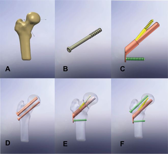
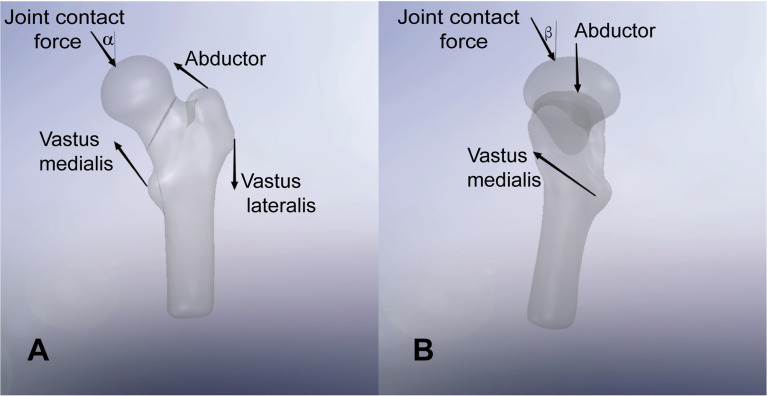
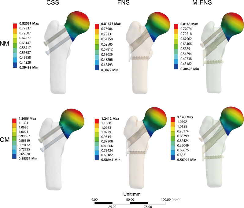
Methods: The Pauwels type III femoral neck fracture models were reconstructed using finite element numerical techniques. The CSS, FNS, and modified FNS (M-FNS) models were created based on features and parameterization. The various internal fixations were individually assembled with the assigned normal and osteoporotic models. In the static analysis mode, uniform stress loads were imposed on all models. The deformation and stress variations of the femur and internal fixation models were recorded. Simultaneously, descriptions of shear stress and strain energy were also incorporated into the figures.
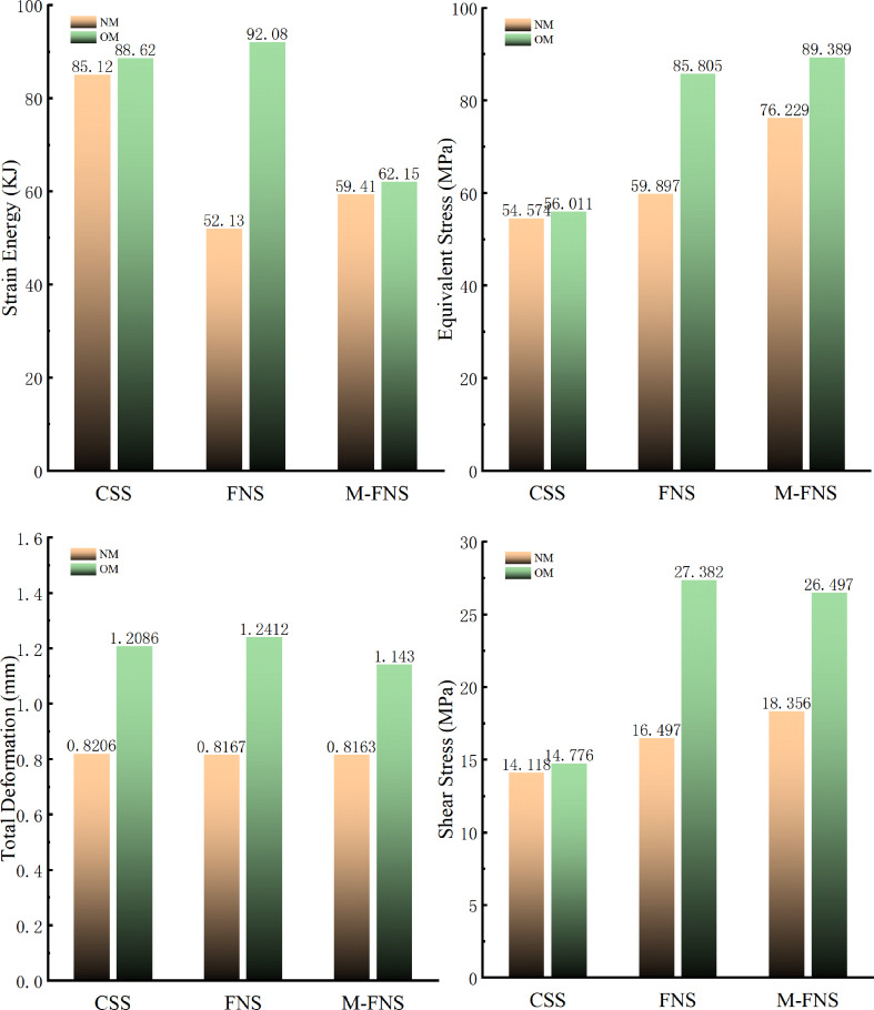
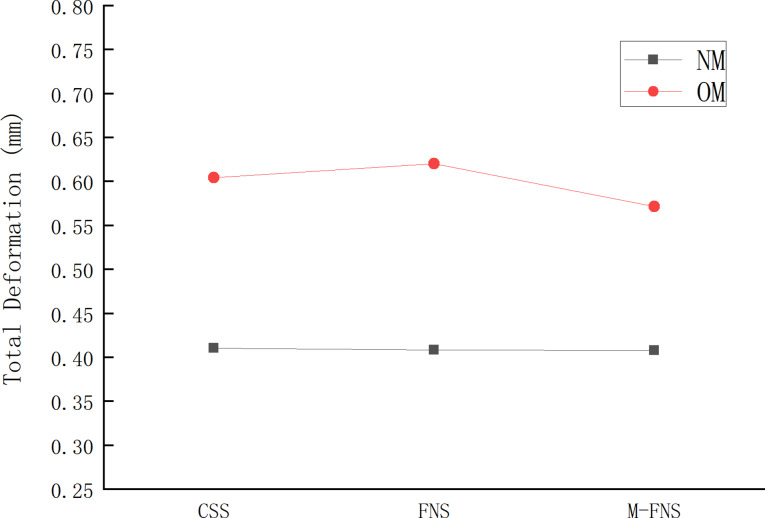
Results: Following bone mass reduction, deformations in CSS, FNS, and M-FNS increased by 47%, 52%, and 40%, respectively. The equivalent stress increments for CSS, FNS, and M-FNS were 3%, 43%, 17%, respectively. Meanwhile, variations in strain energy and shear stress were observed. The strain energy increments for CSS, FNS, and M-FNS were 4%, 76%, and 5%, respectively. The shear stress increments for CSS, FNS, and M-FNS were 4%, 65% and 44%, respectively. Within the osteoporotic model, M-FNS demonstrated the lowest total displacement, shear stress, and strain energy.
Conclusion: Modified FNS showed better stability in the osteoporotic model (OM). Using FNS alone may not exhibit immediate shear resistance advantages in OM. Concurrently, the addition of one anti-rotation screw can be regarded as a potential optimization choice, ensuring a harmonious alignment with the structural characteristics of FNS.
Keywords: Femoral neck fractures; Femoral neck system; Finite element analysis; Osteoporosis.
© 2024. The Author(s).
Conflict of interest statement
The authors declare no competing interests.
Figures


References
-
- Patel S, Kumar V, Baburaj V, Dhillon MS. The use of the femoral neck system (FNS) leads to better outcomes in the surgical management of femoral neck fractures in adults compared to fixation with cannulated screws: a systematic review and meta-analysis. Eur J Orthop Surg Traumatol. 2023;33(5):2101–9. - DOI - PubMed
MeSH terms
Grants and funding
LinkOut - more resources
Full Text Sources
Medical
