

Environmentally Controlled Microfluidic System Enabling Immune Cell Flow and Activation in an Endothelialised Skin-On-Chip
- PMID: 39370595
- PMCID: PMC11582514
- DOI: 10.1002/adhm.202400750
Environmentally Controlled Microfluidic System Enabling Immune Cell Flow and Activation in an Endothelialised Skin-On-Chip
Abstract
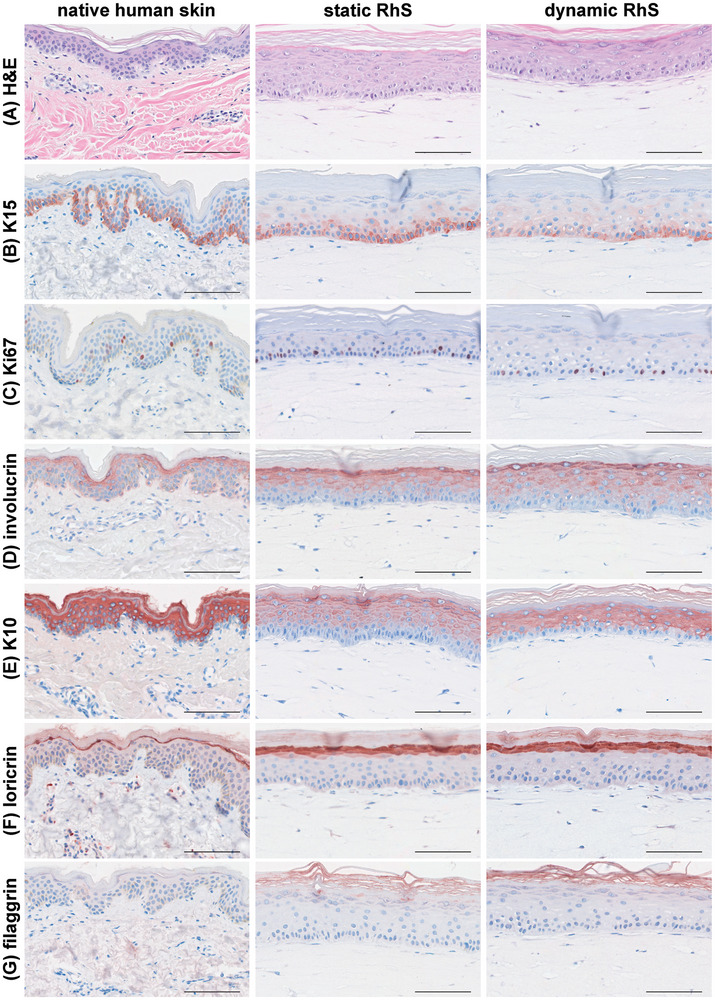
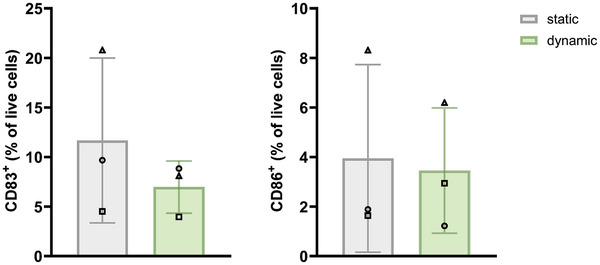
Integration of reconstructed human skin (RhS) into organ-on-chip (OoC) platforms addresses current limitations imposed by static culturing. This innovation, however, is not without challenges. Microfluidic devices, while powerful, often encounter usability, robustness, and gas bubble issues that hinder large-scale high-throughput setups. This study aims to develop a novel re-usable multi-well microfluidic adaptor (MMA) with the objective to provide a flexible tool for biologists implementing complex 3D biological models (e.g., skin) while enabling simultaneous user control over temperature, medium flow, oxigen (O2), nitrogen (N2), and carbon dioxide (CO2) without the need for an incubator. The presented MMA device is designed to be compatible with standard, commercially available 6-well multi-well plates (6MWPs) and 12-well transwells. This MMA-6MWP setup is employed to generate a skin-on-chip (SoC). RhS viability is maintained under flow for three days and their morphology closely resembles that of native human skin. A proof-of-concept study demonstrates the system's potential in toxicology applications by combining endothelialised RhS with flowing immune cells. This dynamic setting activates the monocyte-like MUTZ-3 cells (CD83 and CD86 upregulation) upon topical exposure of RhS to a sensitizer, revealing the MMA-6MWP's unique capabilities compared to static culturing, where such activation is absent.
Keywords: immune cell activation; immune cell flow; microfluidics; organ‐on‐chip; reconstructed human skin; skin‐on‐chip.
© 2024 The Author(s). Advanced Healthcare Materials published by Wiley‐VCH GmbH.
Conflict of interest statement
Matteo Boninsegna, Dario Fassini, Pierre Gaudriault, Jeremy Cramer, and Antoni Homs‐Corbera have been or are currently affiliated with Cherry Biotech SAS, a French SME based in Montreuil commercializing instrumentation for accurate control and monitoring of in vitro systems aimed to provide reliable alternative methods to animal testing to the pharma and biotech industries. All other authors have no conflict of interest to declare.
Figures


Similar articles
-
Implementing organ-on-chip in a next-generation risk assessment of chemicals: a review.Arch Toxicol. 2022 Mar;96(3):711-741. doi: 10.1007/s00204-022-03234-0. Epub 2022 Feb 1. Arch Toxicol. 2022. PMID: 35103818 Free PMC article. Review.
-
Toxicity of topically applied drugs beyond skin irritation: Static skin model vs. Two organs-on-a-chip.Int J Pharm. 2020 Nov 15;589:119788. doi: 10.1016/j.ijpharm.2020.119788. Epub 2020 Aug 31. Int J Pharm. 2020. PMID: 32882369
-
A Multi-Organ-on-Chip Approach to Investigate How Oral Exposure to Metals Can Cause Systemic Toxicity Leading to Langerhans Cell Activation in Skin.Front Toxicol. 2022 Feb 15;3:824825. doi: 10.3389/ftox.2021.824825. eCollection 2021. Front Toxicol. 2022. PMID: 35295125 Free PMC article. Review.
-
A new microfluidic method enabling the generation of multi-layered tissues-on-chips using skin cells as a proof of concept.Sci Rep. 2021 Jun 23;11(1):13160. doi: 10.1038/s41598-021-91875-z. Sci Rep. 2021. PMID: 34162909 Free PMC article.
-
Proof-of-Concept Organ-on-Chip Study: Topical Cinnamaldehyde Exposure of Reconstructed Human Skin with Integrated Neopapillae Cultured under Dynamic Flow.Pharmaceutics. 2022 Jul 22;14(8):1529. doi: 10.3390/pharmaceutics14081529. Pharmaceutics. 2022. PMID: 35893784 Free PMC article.
Cited by
-
Biological Barrier Models-on-Chips: A Novel Tool for Disease Research and Drug Discovery.Biosensors (Basel). 2025 May 26;15(6):338. doi: 10.3390/bios15060338. Biosensors (Basel). 2025. PMID: 40558420 Free PMC article. Review.
-
Replicating Dynamic Immune Responses at Single-Cell Resolution within a Microfluidic Human Skin Equivalent.Adv Sci (Weinh). 2025 Mar;12(10):e2415717. doi: 10.1002/advs.202415717. Epub 2025 Jan 21. Adv Sci (Weinh). 2025. PMID: 39836544 Free PMC article.
-
Biomimetic gender-specific human skin model based on gonads/epidermis-on-a-chip.Bioact Mater. 2025 Jul 15;53:240-252. doi: 10.1016/j.bioactmat.2025.07.014. eCollection 2025 Nov. Bioact Mater. 2025. PMID: 40697396 Free PMC article.
-
Exploring the Complexity of Cutaneous Squamous CellCarcinoma Microenvironment: Focus on Immune Cell Roles by Novel 3D In Vitro Models.Life (Basel). 2025 Jul 23;15(8):1170. doi: 10.3390/life15081170. Life (Basel). 2025. PMID: 40868818 Free PMC article. Review.
-
Gum-on-a-Chip Exploring Host-Microbe Interactions: Periodontal Disease Modeling and Drug Discovery.J Tissue Eng. 2025 Mar 12;16:20417314251314356. doi: 10.1177/20417314251314356. eCollection 2025 Jan-Dec. J Tissue Eng. 2025. PMID: 40078219 Free PMC article.
References
-
- Marx U., Akabane T., Andersson T. B., Baker E., Beilmann M., Beken S., Brendler‐Schwaab S., Cirit M., David R., Dehne E. M., Durieux I., Ewart L., Fitzpatrick S. C., Frey O., Fuchs F., Griffith L. G., Hamilton G. A., Hartung T., Hoeng J., Hogberg H., Hughes D. J., Ingber D. E., Iskandar A., Kanamori T., Kojima H., Kuehnl J., Leist M., Li B., Loskill P., Mendrick D. L., et al., ALTEX 2020, 37, 365. - PMC - PubMed
-
- Low L. A., Mummery C., Berridge B. R., Austin C. P., Tagle D. A., Nat Rev Drug Discov 2021, 20, 345. - PubMed
-
- Leung C. M., de Haan P., Ronaldson‐Bouchard K., Kim G.‐A., Ko J., Rho H. S., Chen Z., Habibovic P., Jeon N. L., Takayama S., Shuler M. L., Vunjak‐Novakovic G., Frey O., Verpoorte E., Toh Y. C., Nat Rev Methods Primers 2022, 2, 33.
MeSH terms
Grants and funding
LinkOut - more resources
Full Text Sources
