. 2024 Oct 9;24(19):6488.
doi: 10.3390/s24196488.

Intelligent Method of Identifying the Nonlinear Dynamic Model for Helicopter Turboshaft Engines

Affiliations

Intelligent Method of Identifying the Nonlinear Dynamic Model for Helicopter Turboshaft Engines

Serhii Vladov et al. Sensors (Basel). .

Abstract

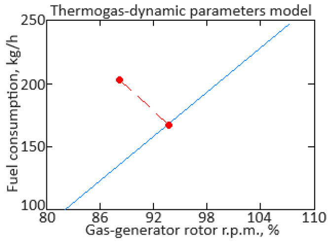
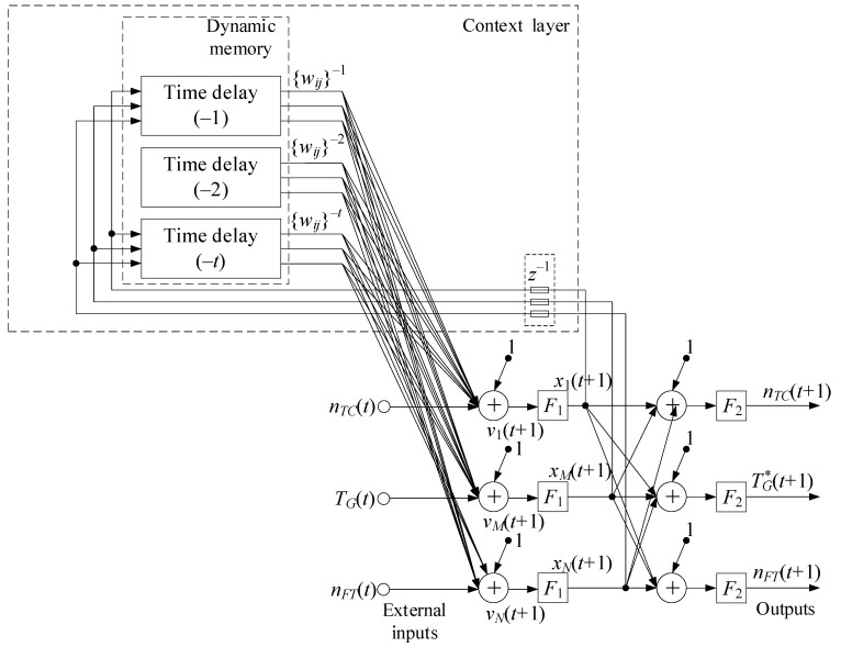
This research focused on the helicopter turboshaft engine dynamic model, identifying task solving in unsteady and transient modes (engine starting and acceleration) based on sensor data. It is known that about 85% of helicopter turboshaft engines operate in steady-state modes, while only around 15% operate in unsteady and transient modes. Therefore, developing dynamic multi-mode models that account for engine behavior during these modes is a critical scientific and practical task. The dynamic model for starting and acceleration modes has been further developed using on-board parameters recorded by sensors (gas-generator rotor r.p.m., free turbine rotor speed, gas temperature in front of the compressor turbine, fuel consumption) to achieve a 99.88% accuracy in identifying the dynamics of these parameters. An improved Elman recurrent neural network with dynamic stack memory was introduced, enhancing the robustness and increasing the performance by 2.7 times compared to traditional Elman networks. A theorem was proposed and proven, demonstrating that the total execution time for N Push and Pop operations in the dynamic stack memory does not exceed a certain value O(N). The training algorithm for the Elman network was improved using time delay considerations and Butterworth filter preprocessing, reducing the loss function from 2.5 to 0.12% over 120 epochs. The gradient diagram showed a decrease over time, indicating the model's approach to the minimum loss function, with optimal settings ensuring the stable training.

Keywords: Elman recurrent neural network with dynamic stack memory; accuracy; dynamic model; engine starting and acceleration; helicopter turboshaft engines; identifying; sensors; training.


Conflict of interest statement

The authors declare no conflicts of interest.

Figures

Figure 1
Figure 1
Diagrams of changes in the helicopter turboshaft engine parameters (using for example, the TV3-117 engine) at starting mode: (a) fuel consumption, (b) gas-generator rotor r.p.m., (c) free turbine rotor speed, (d) gas temperature in front of the compressor turbine (author’s research).
Figure 2
Figure 2
Diagram of changes in the helicopter turboshaft engine’s (using for example, the TV3-117 engine) gas temperature in front of the compressor turbine after applying the low-frequency filtering procedure at starting mode (author’s research).
Figure 3
Figure 3
The dependency diagrams of the helicopter turboshaft engine parameters: (a) fuel consumption, (b) gas-generator rotor r.p.m. (author’s research).
Figure 4
Figure 4
The statistical characteristics of the helicopter turboshaft engine parameters (author’s research).
Figure 5
Figure 5
Implementation diagram of a memory layer for a modified Elman neural network with dynamic stack memory ([76], p. 134, URL: https://swsys.ru/index.php?page=article&id=3910&lang=.docs (accessed on 28 June 2024)).
Figure 6
Figure 6
Modified Elman neural network with dynamic stack memory as a helicopter TE dynamic model (author’s research).
Figure 7
Figure 7
The TV3-117 turboshaft engine parameters’ dynamics time series using digitized oscillograms. (Black curve) Gas-generator rotor r.p.m; (Blue curve) free turbine rotor speed; (Orange curve) gas temperature in front of the compressor turbine (author’s research).
Figure 8
Figure 8
Cluster analysis results: (a) training set, (b) test set (author’s research).
Figure 9
Figure 9
Diagram of the helicopter turboshaft engines parameters (using the TV3-117 engine as an example) after the low-frequency filtering procedure with an eighth-order Butterworth filter: (a): gas-generator rotor r.p.m; (b) free turbine rotor speed; (c) gas temperature in front of the compressor turbine (author’s research).
Figure 10
Figure 10
Diagrams of the spectral characteristics of the helicopter turboshaft engine parameters (using the TV3-117 engine as an example): (a) gas-generator rotor r.p.m., (b) free turbine rotor speed, (c) gas temperature in front of the compressor turbine (author’s research).
Figure 11
Figure 11
Scheme of the training sample loading of the helicopter turboshaft engine’s thermogas-dynamic parameters and the processing of experimental data by the proposed algorithm (author’s research).
Figure 12
Figure 12
Diagrams of the transient processes of the helicopter turboshaft engine parameters at starting mode (using the TV3-117 engine as an example): (a) gas-generator rotor r.p.m., (b) free turbine rotor speed, (c) gas temperature in front of the compressor turbine (author’s research).
Figure 13
Figure 13
Diagrams of the difference between the simulated and experimental processes of the helicopter turboshaft engine at starting mode (using the TV3-117 engine as an example): (a) gas-generator rotor r.p.m., (b) free turbine rotor speed, (c) gas temperature in front of the compressor turbine (author’s research).
Figure 14
Figure 14
Diagrams of the transient processes of the helicopter turboshaft engine parameters at acceleration mode (using the TV3-117 engine as an example): (a) gas-generator rotor r.p.m., (b) free turbine rotor speed, (c) gas temperature in front of the compressor turbine (author’s research).
Figure 15
Figure 15
Diagrams of the difference between the simulated and experimental processes of the helicopter turboshaft engine at acceleration mode (using the TV3-117 engine as an example): (a) gas-generator rotor r.p.m., (b) free turbine rotor speed, (c) gas temperature in front of the compressor turbine (author’s research).
Figure 16
Figure 16
Diagram of the influence of epoch number passed the mean square error (author’s research).
Figure 17
Figure 17
Diagram of accuracy metric (author’s research).
Figure 18
Figure 18
Diagram of loss function (author’s research).
Figure 19
Figure 19
Diagram of changes in loss function gradients (author’s research).
Figure 20
Figure 20
Diagrams of the distribution surfaces U1(k) (a), U2(k) (b), and U3(k) (c) (author’s research).
Figure 21
Figure 21
The resulting k-fold cross-validation diagrams (author’s research).
Figure 22
Figure 22
The AUC-ROC curves. (a) Proposed modified Elman neural network with dynamic stack memory; (b) traditional Elman neural network developed in [34,66]; (c) cubic spline interpolation (author’s research).

References

    1. Balli O. Exergetic, sustainability and environmental assessments of a turboshaft engine used on helicopter. Energy. 2023;276:127593. doi: 10.1016/j.energy.2023.127593. - DOI
    1. Zhang S., Ma A., Zhang T., Ge N., Huang X. A Performance Simulation Methodology for a Whole Turboshaft Engine Based on Throughflow Modelling. Energies. 2024;17:494. doi: 10.3390/en17020494. - DOI
    1. Ahmadian N., Khosravi A., Sarhadi P. Adaptive control of a jet turboshaft engine driving a variable pitch propeller using multiple models. Mech. Syst. Signal Process. 2017;92:1–12. doi: 10.1016/j.ymssp.2017.01.023. - DOI
    1. Zheng X., Zeng H., Wang B., Wen M., Yang H., Sun Z. Numerical simulation method of surge experiments on gas turbine engines. Chin. J. Aeronaut. 2023;36:107–120. doi: 10.1016/j.cja.2022.08.007. - DOI
    1. Chen M., Qu R., Fang W. Case-based reasoning system for fault diagnosis of aero-engines. Expert Syst. Appl. 2022;202:117350. doi: 10.1016/j.eswa.2022.117350. - DOI

LinkOut - more resources