Review
. 2024 Oct 18:5:0172.
doi: 10.34133/cbsystems.0172. eCollection 2024.

Advances in Biointegrated Wearable and Implantable Optoelectronic Devices for Cardiac Healthcare

Affiliations
Review

Advances in Biointegrated Wearable and Implantable Optoelectronic Devices for Cardiac Healthcare

Cheng Li et al. Cyborg Bionic Syst. .

Abstract

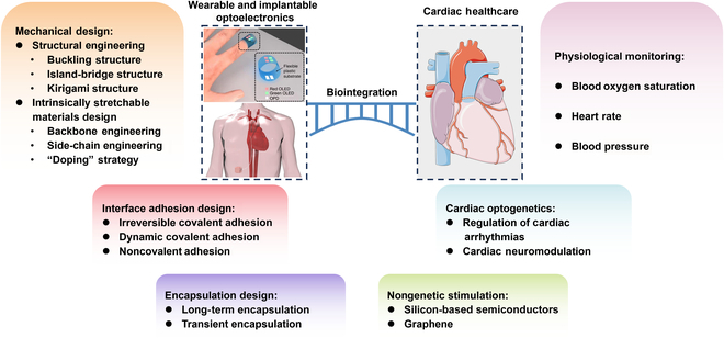
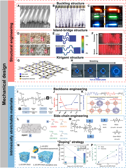
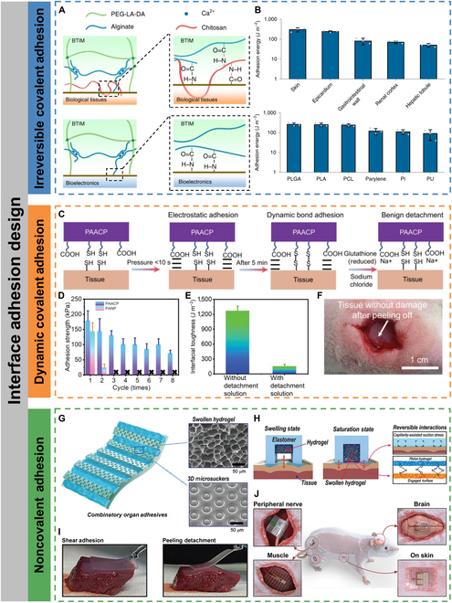
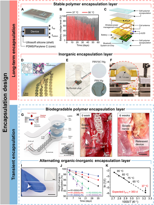
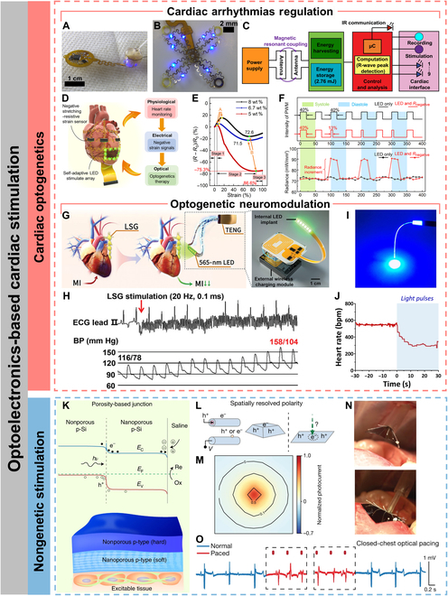
With the prevalence of cardiovascular disease, it is imperative that medical monitoring and treatment become more instantaneous and comfortable for patients. Recently, wearable and implantable optoelectronic devices can be seamlessly integrated into human body to enable physiological monitoring and treatment in an imperceptible and spatiotemporally unconstrained manner, opening countless possibilities for the intelligent healthcare paradigm. To achieve biointegrated cardiac healthcare, researchers have focused on novel strategies for the construction of flexible/stretchable optoelectronic devices and systems. Here, we overview the progress of biointegrated flexible and stretchable optoelectronics for wearable and implantable cardiac healthcare devices. Firstly, the device design is addressed, including the mechanical design, interface adhesion, and encapsulation strategies. Next, the practical applications of optoelectronic devices for cardiac physiological monitoring, cardiac optogenetics, and nongenetic stimulation are presented. Finally, an outlook on biointegrated flexible and stretchable optoelectronic devices and systems for intelligent cardiac healthcare is discussed.


Conflict of interest statement

Competing interests: The authors declare that they have no competing interests.

Figures

Fig. 1.
Fig. 1.
Biointegrated wearable and implantable optoelectronic devices for cardiac healthcare. Mechanical, interface adhesion, and encapsulation design strategies for wearable and implantable optoelectronic devices (left). Cardiac healthcare applications of wearable and implantable optoelectronic systems for cardiac physiological monitoring, cardiac optogenetics, and nongenetic stimulation (right). The figures in “Wearable and implantable optoelectronics”. Reproduced with permission from [91]. Copyright 2014, Springer Nature Limited (top). Reproduced under the terms of the Creative Commons CC-BY-NC license from [95]. Copyright 2021 The American Association for the Advancement of Science (bottom).
Fig. 2.
Fig. 2.
Mechanical design for stretchability. (A) Perspective scanning electron micrograph of a buckling-structured LED. (B) Optical image of the buckling-structured LED under 70% tensile strain along the horizontal direction. (C) Photographs of the stretchable red, green, and blue buckling-structured LEDs at strains of 0% and 70%, respectively. Reproduced with permission from [39]. Copyright 2017 American Chemical Society. (D) Stretchable μ-LEDs adopting the island-bridge approach. (E) Strain distribution simulated by finite element method on the stretchable μ-LEDs based on island-bridge structure. (F) Photography of the stretchable μ-LEDs under uniaxial strain (top 0%, bottom 40%). Reproduced with permission from [48]. Copyright 2017 WILEY-VCH Verlag GmbH & Co. KGaA, Weinheim. (G) Schematic illustration of morphable displays transforming from 2D precursors to 3D structures under strain. (H) Optical images show the morphable display with the real-time automatic feedback system exhibiting character “O” when stretching. Reproduced with permission from [42]. Copyright 2022 Elsevier Ltd. (I) Chemical structures of DPP-based semiconducting polymers containing 10 mol% of conjugation breakers. (J) Elastic modulus and crack onset strain of the polymer semiconductors. Reproduced with permission from [56]. Copyright 2018 WILEY-VCH Verlag GmbH & Co. KGaA, Weinheim. (K) Chemical structure of PDMS–MPUx–IU1−x (top) and possible hydrogen bonding combinations for strong bond and weak bond, respectively (bottom). Reproduced with permission from [65]. Copyright 2018 WILEY-VCH Verlag GmbH & Co. KGaA, Weinheim. (L) Schematics of PDPPT polymers with different side-chain structures. Reproduced with permission from [59]. Copyright 2021 Wiley-VCH GmbH. (M) Schematics of the chemical structure of the DPP-based polymers and their respective side-chain H-bonding groups 2,6-pyridinedicarboxamide (PDCA) units. Reproduced with permission from [60]. Copyright 2019 American Chemical Society. (N) 3D schematic of the morphology comprising embedded 3D penetrating nanonetworks of L-SY-PPV/PAN. (O) Derjauin−Muller−Toporov (DMT) modulus and the crack onset strain (COS) results for the L-SY-PPV/PAN mixed film with different PAN contents. (P) Hole and electron mobilities in the L-SY-PPV/PAN mixed film with different PAN contents. Reproduced with permission from [63]. Copyright 2022 Wiley-VCH GmbH.
Fig. 3.
Fig. 3.
Interface adhesion design. (A) Mechanisms of BTIM bonding to the surfaces of biological tissues (top) and bioelectronic devices (bottom). (B) Adhesion energy between BTIM and a variety of tissues and device surfaces. Reproduced with permission from [67]. Copyright 2021 The Authors, under exclusive license to Springer Nature Limited. (C) Schematic of PAACP adhesion and detachment mechanisms. (D) Adhesion strengths obtained for 8 continuously repeated adhesion tests. (E) Influence of detachment solution on PAACP interfacial toughness. (F) Photograph of muscle without damage after on-demand and benign detachment of PAACP by using detachment solution (implanted into the subcutaneous muscle of the rat for 14 d). Reproduced with permission from [69]. Copyright 2023 Wiley-VCH GmbH. (G) Schematic illustration of the multiscale combinatory organ adhesion with swollen hydrogel and 3D microsuckers. (H) Adhesive mechanism of the combinatory organ adhesion via mechanical interaction of capillarity-assisted suction stress and hydrogel absorption and swelling, which induces multiple-point hydrogen bonds between the hydrogel and proteins on the tissue surface. (I) Demonstration of strong shear adhesion and facile peeling detachment of a combinatory organ adhesion on a liver surface. (J) Schematic illustration of the integrated adhesive electronics adhered to various organs (peripheral nerve, brain, muscle, and skin). Reproduced with permission from [71]. Copyright 2021 Wiley-VCH GmbH.
Fig. 4.
Fig. 4.
Encapsulation design. (A) Schematic diagram of an implant encapsulated with soft biocompatible polymers (top) and its cross-sectional view (bottom). (B) Battery voltage level as a function of time during repeated wireless charging (60 min) and μ-ILED operating (20 Hz, 10-ms pulse width) after immersing the devices in saline water with temperatures of 37 and 90 °C. (C) Exploded-view schematic diagram of a soft wireless optoelectronic system with bilateral probes, consisting of μ-ILEDs, a power management circuit, radiofrequency coil antennas, a battery, and a Bluetooth Low Energy System-on-Chip. Reproduced under the terms of the Creative Commons CC BY license from [74]. Copyright 2021 The Authors. (D) Flexible SiC-on-PI devices wrapped around a curved surface (diameter = 12 mm). (E) Photograph of SiC/PI immersing at PBS at pH 7.4 and 96 °C. (F) Photograph of SiC/PI upon several bending cycles. Reproduced with permission from [76]. Copyright 2019 American Chemical Society. (G) Schematic illustration of the device consisting of an interlayer (b-DCPU, 50 μm thick), a stimulation cuff (PLGA, 30 μm thick), etc. All parts of the system, excluding the stimulation cuff, are sandwiched between 2 layers of bioresorbable elastomers (b-DCPU, 100 μm). The schematic illustration in the inset shows the contact between the nerve and the stimulation cuff (bottom, right) (H) Images of the release device from the bioresorbable stimulator on the sciatic nerve after 6 weeks. Reproduced under the terms of the Creative Commons CC BY license from [79]. Copyright 2020 The Authors. (I) Photographs of a 3-layer SiON-PA film. Scale bars, 1 cm. (J) Degradation behavior of PA (thickness, 100 μm) with different compositions. (K) Arrhenius plot of the temperature-dependent degradation of 3-layer SiON-PA films. Reproduced under the terms of the Creative Commons CC BY license from [80]. Copyright 2024 The Authors.
Fig. 5.
Fig. 5.
Cardiac physiology monitoring. (A) Photograph of a finger with the ultraflexible organic optical sensor attached (left) and operation principle of the reflective pulse oximeter (right). Reproduced under the terms of the Creative Commons CC-BY-NC license from [92]. Copyright 2016 The Authors. (B) Image of a device during operation while mounted on a thumbnail (bottom) and exploded-view schematic illustration of the various constituent layers of a millimeter-scale, NFC-enabled pulse oximeter device (top). Reproduced with permission from [94]. Copyright 2016 WILEY-VCH Verlag GmbH & Co. KGaA, Weinheim. (C) Image of a catheter oximeter wrapped around a glass rod (left) and the enlarged image of the sensor probe encapsulated with transparent, biocompatible silicone (right). Reproduced under the terms of the Creative Commons CC-BY-NC license from [95]. Copyright 2021 The Authors. (D) Schematic of an SHP attached to the forearm to measure the HR from the wrist (left) and schematic layout of a single pixel on the stretchable substrate (right). (E) Digital image of a fully integrated SHP comprising an organic stretchable PPG sensor, stretchable OLED display, processing module, and thin bendable battery (scale bar, 1 cm). (F) Digital image of the SHP under operation. The HR measured by the PPG sensor is displayed in real time on the green OLED array. Reproduced under the terms of the Creative Commons CC-BY-NC license from [96]. Copyright 2021 The Authors. (G) Photograph of a finger covered with the epidermal PPG sensor (scale bar, 5 mm) (bottom) and schematic of the device structure of the flexible OPT (top). Reproduced with permission from [97]. Copyright 2017 WILEY-VCH Verlag GmbH & Co. KGaA, Weinheim. (H) Schematic illustration of the skin-like device integrated with a flexible circuit for monitoring arterial pressure. (I) Processing steps of the optical difference in the time domain (FFT, fast Fourier transform; IFFT, inverse fast Fourier transform). Reproduced under the terms of the Creative Commons CC BY license from [101]. Copyright 2020 The Authors. (J) Schematic of a polarization-selective sensor. (K) Reflected light in a sensor with an orthogonal polarizer–analyzer pair. (L) Ratio between the peak intensity at ~0.5 Hz (motion artifact) and ~1.1 Hz (heartbeat) during wrist movement over wrist angles ranging from −1° to +1° (±1°), −5° to + 5° (±5°), −10° to +10° (±10°), −20° to +20° (±20°), −30° to +30° (±30°), and −40° to +40° (±40°). Reproduced under the terms of the Creative Commons CC-BY-NC license from [102]. Copyright 2022 The Authors.
Fig. 6.
Fig. 6.
Optoelectronics-based cardiac stimulation. (A) Photographic image of multisite pacing of ex vivo ChR2-expressing mouse heart. (B) Photographic image of μ-ILED and recording array. (C) Schematic diagram of operating electrical principles. Reproduced under the terms of the Creative Commons CC-BY-NC license from [21]. Copyright 2022 The Authors. (D) Schematic illustration of a self-adaptive implantable cardiac optogenetics system based on an original negative stretching-resistive strain sensor array. (E) Resistance characteristics of CNL membranes with different carbon nanotube ratios. (F) The duty cycle settings of the pulse width modulation wave of the optogenetics device with single LED and LED in series with negative or positive stretching-resistive sensor, respectively (top) and radiance of the LED without and with negative stretching-resistive strain sensor in different periods of systole and diastole (bottom). Reproduced under the terms of the Creative Commons CC-BY-NC license from [114]. Copyright 2021 The Authors. (G) Schematic illustration of the optogenetic neuromodulation by the self-powered optical system (left) and schematic diagram of the implantable, battery-free wireless optogenetic system. (H) Representative examples of BP elevation in response to LSG stimulation. ECG, electrocardiogram. Reproduced under the terms of the Creative Commons CC BY license from [118]. Copyright 2023 The Authors. (I) A representative image of a POF exhibiting excellent light conductivity. (J) Representative example of the HR variability in anesthetized. Reproduced under the terms of the Creative Commons CC BY license from [121]. Copyright 2021 The Authors. (K) Schematic illustration (bottom) and energy band diagram (top) of the porosity-based junction. Reproduced with permission from [122]. Copyright 2022, The Authors, under exclusive license to Springer Nature Limited. (L) Optically controlled and spatially resolved polarity enables charge balance, allowing cathodic and anodic processes to occur on the same material surface. (M) The normalized photocurrent mapping against the illumination center. (N) Side-view photographs of the endoscopic device-delivery process (scale bars, 1 cm). (O) Paced electrocardiograph waveforms derived from a fully closed-thoracic procedure. Reproduced with permission from [123]. Copyright 2024, The Authors, under exclusive license to Springer Nature Limited.

References

    1. Xu H, Yin L, Liu C, Sheng X, Zhao N. Recent advances in biointegrated optoelectronic devices. Adv Mater. 2018;30(33):1800156. - PubMed
    1. Song JK, Kim MS, Yoo S, Koo JH, Kim DH. Materials and devices for flexible and stretchable photodetectors and light-emitting diodes. Nano Res. 2021;14(9):2919–2937.
    1. Jacoutot P, Scaccabarozzi AD, Nodari D, Panidi J, Qiao Z, Schiza A, Nega AD, Dimitrakopoulou-Strauss A, Gregoriou VG, Heeney M, et al. Enhanced sub-1 eV detection in organic photodetectors through tuning polymer energetics and microstructure. Sci Adv. 2023;9(23):eadh2694. - PMC - PubMed
    1. Sunwoo SH, Han SI, Park CS, Kim JH, Georgiou JS, Lee SP, Kim DH, Hyeon T. Soft bioelectronics for the management of cardiovascular diseases. Nat Rev Bioeng. 2023;2:8–24.
    1. Sunwoo SH, Ha KH, Lee S, Lu N, Kim DH. Wearable and implantable soft bioelectronics: Device designs and material strategies. Annu Rev Chem Biomol Eng. 2021;12:359–391. - PubMed

LinkOut - more resources