

Power electronics for green hydrogen generation with focus on methods, topologies, and comparative analysis
- PMID: 39433917
- PMCID: PMC11494192
- DOI: 10.1038/s41598-024-76191-6
Power electronics for green hydrogen generation with focus on methods, topologies, and comparative analysis
Abstract
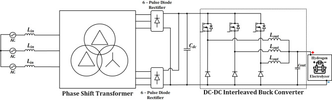
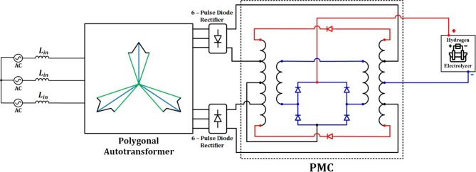
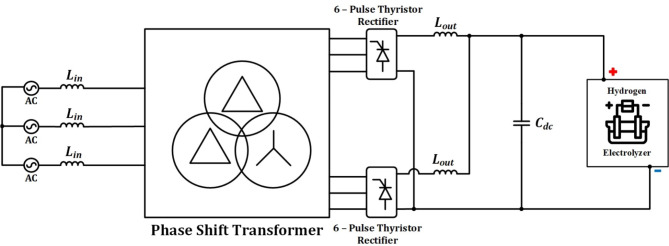
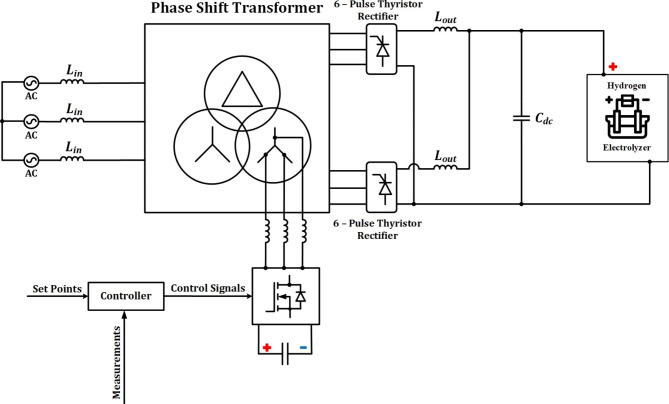
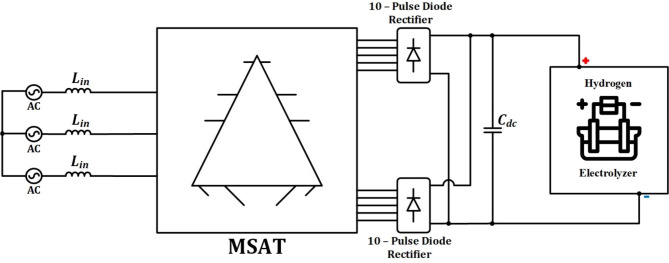
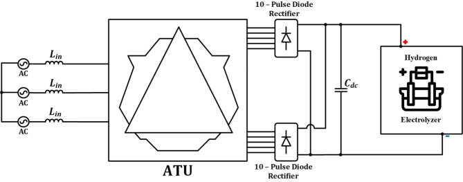
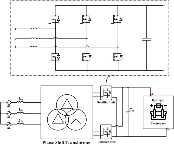
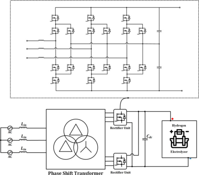
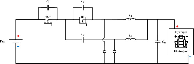
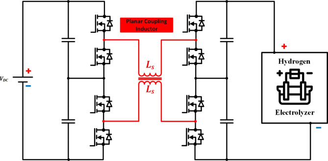
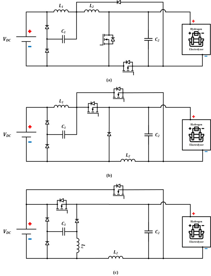
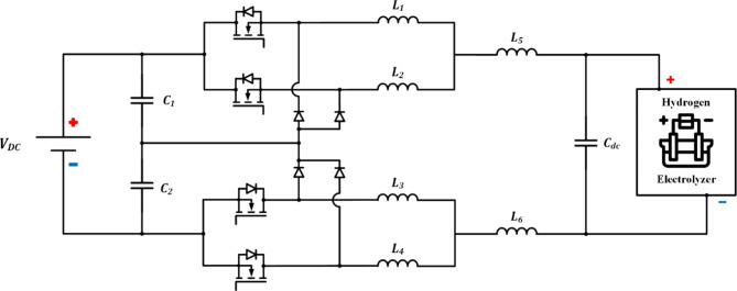
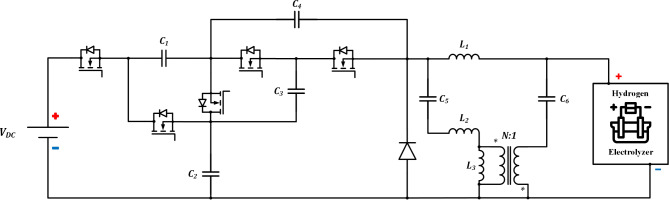
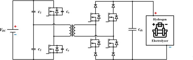
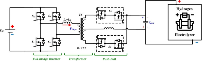
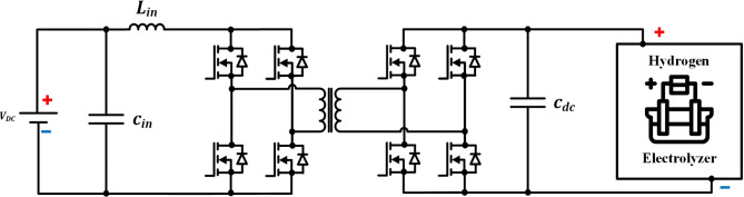
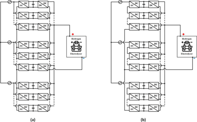
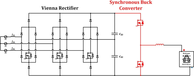
This research article meticulously examines advanced power electronic converters crucial for optimizing electrolyzer perfor- mance in hydrogen production systems. It conducts a thorough review of mature electrolyzer types, detailing their specifications, electric models, manufacturers, and scalability. To meet the high current and stable DC voltage demands of industrial electrolyzers, the study delves into a broad spectrum of AC-DC and DC-DC converter topologies. It explores cutting-edge solutions like 12-pulse and 20-pulse rectifiers, advanced higher multi-pulse rectifiers utilizing conventional and auto-connected transformer units, Multi-Step Auto-connected Transformers (MSAT), polygon autotransformers, and auxiliary filters and circuits such as pulse multiplication circuits and active power filters. These innovations significantly reduce harmonic distortions and enhance power quality, addressing challenges inherent in conventional 6-pulse diode bridge rectifiers. The research also focuses on the efficiency and power factor correction capabilities of Active Front End (AFE) converters and the 3L-DNPC rectifier. Additionally, it investigates various DC-DC converters, including the Continuous Input Current Non-Isolated Bidirec- tional Interleaved Buck-Boost DC-DC Converter, the Interleaved Buck Converter (IBC) with extended duty cycles, the 3-level buck-boost converter with a coupled inductor, Quadratic converters designed for fault tolerance, the three-level interleaved buck converter, among others. Converter designs like the galvanically isolated half-bridge converter with controlled reverse-blocking switches for achieving zero voltage switching (ZVS), the Push-Pull isolated DC-DC converter prioritizing current stability, and the Isolated Full-Bridge Boost Converter (IFBBC) adept at handling fluctuating power outputs from renewable sources are also explored. Moreover, the study scrutinizes a range of converter configurations such as the Two-stage ZVT boost converter with LCL-Type SRC, multiphase interleaved DC-DC stage, and three-port isolated DC/DC converter for efficient integration with multiple energy sources concurrently. Discussing feature trends in power-to-hydrogen systems, the research reviews multi-cell modular rectifiers and multi-stage rectifiers. Overall, the study underscores the critical role of advanced converter topologies in enhancing efficiency, reliability, and power quality in electrolyzer systems, thereby contributing significantly to the progression of sustainable energy technologies.
Keywords: 12-pulse rectifiers; Active front end converters; DC-DC converters; Electrolyzers; Harmonic reduction; Interleaved buck converter; Power quality; Zero voltage switching.
© 2024. The Author(s).
Conflict of interest statement
The authors declare no competing interests.
Figures


References
-
- IEA. Global hydrogen review 2022. https://www.iea.org/reports/global-hydrogen-review-2022/.
-
- Salkuyeh, Y. K., Saville, B. A. & MacLean, H. L. Techno-economic analysis and life cycle assessment of hydrogen production from natural gas using current and emerging technologies. Int. J. Hydrogen Energy42, 18894–18909 (2017).
-
- IEA. Global hydrogen review 2021. https://www.iea.org/reports/global-hydrogen-review-2021.
-
- Commission, E. T. et al. Making mission possible-delivering a net zero economy 2020. https://www.energy-transitions.org/publications/making-mission-possible/ (2020).
-
- Greendrogen. A brief history of electrolyzers. https://greendrogen.com/uncategorized/a-brief-history-of-electrolysis/.
LinkOut - more resources
Full Text Sources
Miscellaneous
