. 2024 Oct 8:18:1418125.
doi: 10.3389/fncel.2024.1418125. eCollection 2024.

Mathematical models of C-type and N-type inactivating heteromeric voltage gated potassium channels

Affiliations

Mathematical models of C-type and N-type inactivating heteromeric voltage gated potassium channels

Kees McGahan et al. Front Cell Neurosci. .

Abstract

Voltage gated potassium channels can be composed of either four identical, or different, pore-forming protein subunits. While the voltage gated channels with identical subunits have been extensively studied both physiologically and mathematically, those with multiple subunit types, termed heteromeric channels, have not been. Here we construct, and explore the predictive outputs of, mechanistic models for heteromeric voltage gated potassium channels that possess either N-type or C-type inactivation kinetics. For both types of inactivation, we first build Markov models of four identical pore-forming inactivating subunits. Combining this with previous results regarding non-inactivating heteromeric channels, we are able to define models for heteromeric channels containing both non-inactivating and inactivating subunits of any ratio. We simulate each model through three unique voltage clamp protocols to identify steady state properties. In doing so, we generate predictions about the impact of adding additional inactivating subunits on a total channel's kinetics. We show that while N-type inactivating subunits appear to have a non-linear impact on the level of inactivation the channel experiences, the effect of C-type inactivating subunits is almost linear. Finally, to combat the computational issues of working with a large number of state variables we define model reductions for both types of heteromeric channels. For the N-type heteromers we derive a quasi-steady-state approximation and indicate where the approximation is appropriate. With the C-type heteromers we are able to write an explicit model reduction bringing models of greater than 10 dimensions down to 2.

Keywords: KV channels; Kv1 channels; heteromeric potassium ion channels; ion channel kinetics; mathematical modeling.


Conflict of interest statement

The authors declare that the research was conducted in the absence of any commercial or financial relationships that could be construed as a potential conflict of interest.

Figures
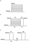
Figure 1
Figure 1
Diagrams of the three different voltage clamp experiments used for model fitting and analysis. (A) The activation protocol begins by holding the membrane potential at −90 mV and then, in increments of 10 mV, steps and holds the membrane potential at some new voltage between −90 mV and 50 mV. (B) The inactivation protocol steps the voltage from −90 mV to a new voltage between −90 mV and 50 mV where it is held for 5s. Then regardless of the initial voltage step, the voltage is increased to 50 mV and held there for 1 second. (C) The recovery protocol performs 2 pulses P1 and P2 which are separated by a variable time duration Δt. In each pulse the membrane potential is stepped from −90 mV to 50 mV.
Figure 2
Figure 2
A Markov model diagram for a homomeric N-type inactivating channel. The states Ci denote the probability of having i subunits in the open state. The probability of being in the conducting state is given by O, where all 4 subunits are in the open state. I is the probability of the channel having an N-ball bound to the pore and being in the inactive state. The kinetic rates a1, b1 give transitions between a single subunit going from closed to open state and vice versa. The rate of a single N-ball binding to the pore is aI and the unbinding is given by bI.
Figure 3
Figure 3
A Markov model diagram for a heteromeric channel with 3 N-type inactivating subunits and 1 non-inactivating subunit. The state Ci, j is the probability of having i N-type inactivating subunits in the open state and j non-inactivating subunits in the open state. The states O, I and rates a1, b1, aI, bI have identical meaning to that of Figure 2. The rates a2 and b2 give the opening and closing transitions for the non-inactivating subunit.
Figure 4
Figure 4
Responses of each heteromeric and homomeric channel with Kv1.4[K532Y] N-type inactivating subunits and KV1.1 non-inactivating subunits to the three voltage clamp protocols of Figure 1. (A) The ratio of the maximum open probability of the channel seen during P2 compared to P1, plotted against the voltage stepped to during P1 based on the inset inactivation protocol. (B) The ratio of the maximum open probability of the channel seen during P2 compared to P1, plotted against the time duration, Δt, between P1 and P2, based on the inset recovery protocol. (C) The maximum open probability of the channel after the voltage step, plotted against the voltage the channel was stepped to. Data point colors are: pink (4 Kv1.4[K532Y] subunits), black (1 KV1.1 to 3 KV1.4[K532Y] subunits), orange (2 KV1.1 to 2 KV1.4[K532Y] subunits), green (3 KV1.1 to KV1.4[K532Y] subunits) and blue (4 KV1.1 subunits).
Figure 5
Figure 5
Experimentally fit kinetic transition rates plotted against a given voltage in mV. The following rates are plotted: opening and closing rates of Kv1.4[K532Y] subunits (a14, b14), opening and closing rates of Kv1.1 (a11, b11), and the binding and unbinding rates of the N-balls, (aI, bI). Curve color and style are given in the figure legend.
Figure 6
Figure 6
A comparison between the full KV1.1:Kv1.4[K532Y] heteromeric models and the QSS reduced KV1.1:Kv1.4[K532Y] heteromeric models by looking at the channel responses to the inactivation protocol (A) and recovery protocol (B). Data point colors correspond to the identical subunit ratio described in Figure 4, with circles the full model data points and triangles the QSS model data points.
Figure 7
Figure 7
Full time simulations of the homomeric full (A) and QSS (B) KV1.4[K532Y] models in response to the activation protocol. Each curve denotes a different voltage that the channels has been held at.
Figure 8
Figure 8
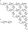
(A) A Markov model diagram for a homomeric channel with 4 C-type inactivating subunits. The state Ci, j is the probability of having i subunits having reached the open state and j of these subunits being inactive. The state O is the conducting state where all 4 subunits are open and none are inactive. Rates a1, b1, aI, bI are the corresponding forward and backward rates of a single C-type inactivating subunit transitioning between closed, open and inactive as is depicted in (B).
Figure 9
Figure 9
A comparison between the (Bett et al., 2011) simulated Kv1.4ΔN homomeric model and our hypothesized Kv1.4ΔN homomeric model. Four unique pieces of information were compared: (A) the open probability curves in response to the activation protocol, (B) the value of the activation time constant τ, (C) the response to the inactivation protocol, and (D) the response to the recovery protocol. The green data points are our model with the best fitting parameter set, and the orange data points are the (Bett et al., 2011) model. The inset diagrams depict the performed voltage clamp protocol.
Figure 10
Figure 10
Markov model diagrams used to describe heteromeric channels with 1 C-type inactivating subunit and 3 non-inactivating subunits. Rates a1, b1, aI, bI are the corresponding forward and backward rates of a single C-type inactivating subunit transitioning between closed, open and inactive as is depicted in (A). Rates a2 and b2 are the corresponding forward and backward rates of a single non-inactivating subunit transiting between closed and open as is depicted in (B). A Markov model diagram for a heteromeric channel with 1 C-type inactivating subunit and 3 non-inactivating subunits (C). The state Ci, j, k is the probability of having i C-type subunits having reached the open state, j C type subunits in the inactive state, and k non-inactivating subunits in the open state. The state O is the conducting state where all 4 subunits are in the openconformation and none are inactive.
Figure 11
Figure 11
Responses of each heteromic and homomeric channel with KV1.4ΔN subunits and KV1.1 subunits to the inactivation and recovery voltage clamp protocols (Figure 1). (A) Identical plot meaning and data point coloring to that of Figure 4A, but with our KV1.1:KV1.4ΔN models. (B) Identical plot meaning and data point coloring to that of Figure 4B, but with our KV1.1:KV1.4ΔN models.

References

    1. Al-Sabi A., Kaza S., Le Berre M., O'Hara L., Bodeker M., Wang J., et al. . (2011). Position-dependent attenuation by kv1.6 of n-type inactivation of kv1.4-containing channels. Biochem. J. 438, 389–396. 10.1042/BJ20102169 - DOI - PubMed
    1. Al-Sabi A., Kaza S. K., Dolly J. O., Wang J. (2013). Pharmacological characteristics of kv1. 1-and kv1. 2-containing channels are influenced by the stoichiometry and positioning of their α subunits. Biochem. J. 454, 101–108. 10.1042/BJ20130297 - DOI - PubMed
    1. Barfield J., Yeung C., Cooper T. (2005). Characterization of potassium channels involved in volume regulation of human spermatozoa. Mol. Hum. Reprod. 11, 891–897. 10.1093/molehr/gah208 - DOI - PubMed
    1. Bett G. C., Dinga-Madou I., Zhou Q., Bondarenko V. E., Rasmusson R. L. (2011). A model of the interaction between n-type and c-type inactivation in kv1.4 channels. Biophys. J. 100, 11–21. 10.1016/j.bpj.2010.11.011 - DOI - PMC - PubMed
    1. Coetzee W. A., Amarillo Y., Chiu J., Chow A., Lau D., McCormack T., et al. . (1999). Molecular diversity of k+ channels. Ann. N. Y. Acad. Sci. 868, 233–255. 10.1111/j.1749-6632.1999.tb11293.x - DOI - PubMed

LinkOut - more resources