. 2019:56:10.1016/j.precisioneng.2018.12.002.
doi: 10.1016/j.precisioneng.2018.12.002.

An invisible-stylus-based coordinate measurement system via scaled orthographic projection

Affiliations

An invisible-stylus-based coordinate measurement system via scaled orthographic projection

Joshua A Gordon et al. Precis Eng. 2019.

Abstract

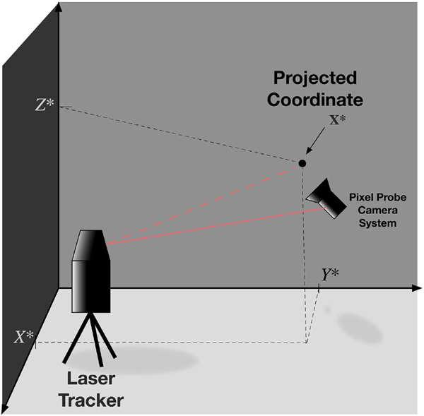
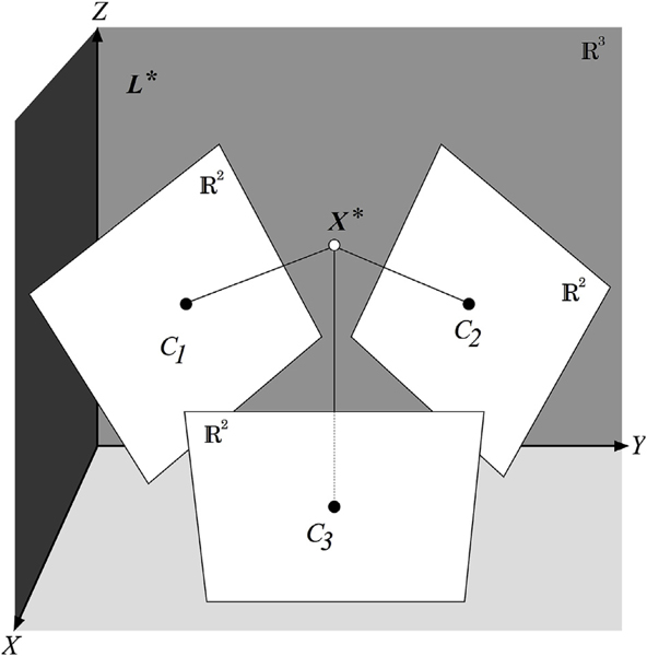
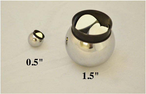
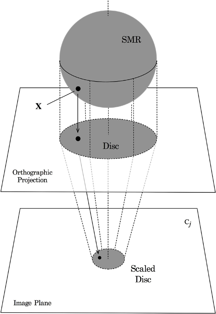
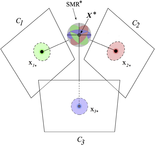
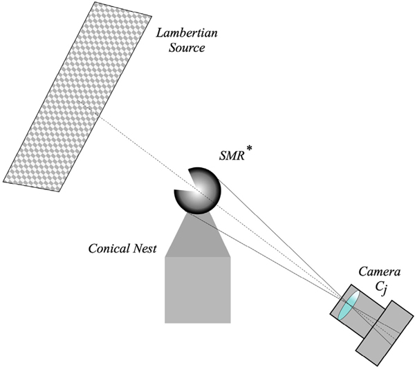
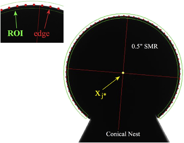
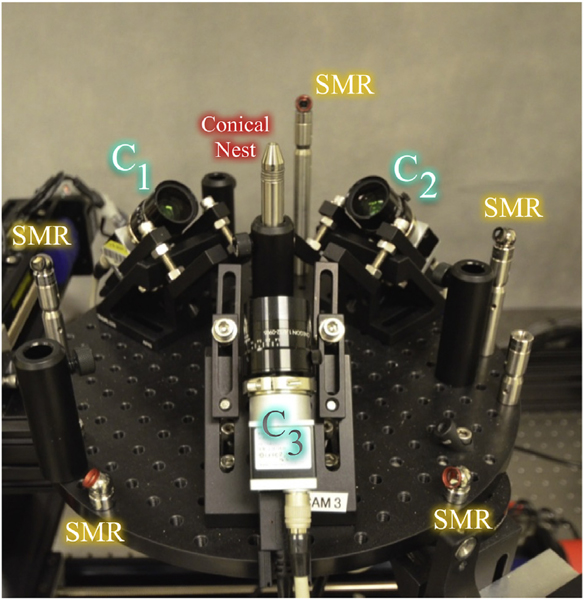
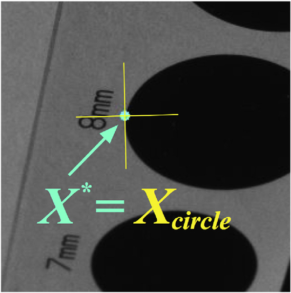
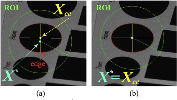
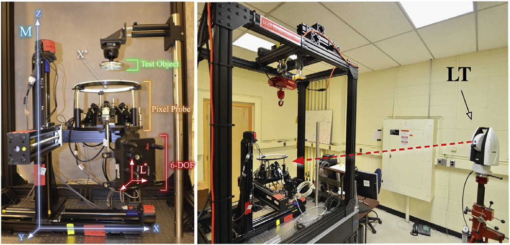
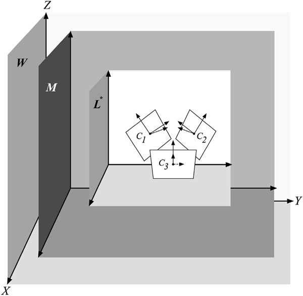
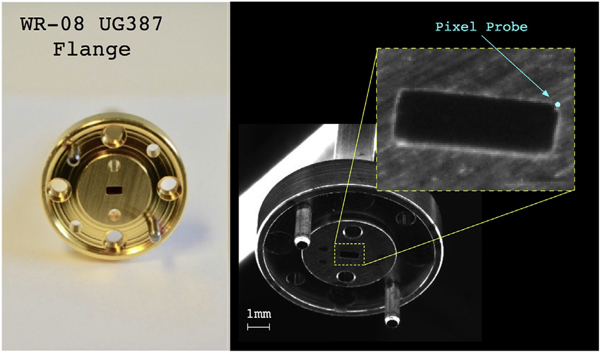
We present on a simple yet effective method for creating an invisible stylus from which a non-contact 3-D coordinated measuring system (the PiCMS) is realized. This invisible stylus dubbed a Pixel Probe is created through the orthographic projection of a spherical mounted reflector (SMR) through a trifocal camera system. Through this, a single point in space that is linked to a laser tracker world frame is mapped to a unique set of pixel coordinates in the trifocal camera creating the Pixel Probe. The system is constructed through the union of a Pixel Probe, a laser tracker, and calibrated XYZ stage, and does not require contact to obtain a measurement. In the current configuration, system resolution and accuracy better than 20 μ m is demonstrated on objects in the meso/micro scale that are well below the range of a laser tracker alone. A simple single-point coincidence condition allows the user to specify a measurement coordinate by pointing-and-clicking in the images captured by the Pixel Probe. We describe this system using multi-view geometry vision theory and present proof of concept measurement examples of 2-D and 3-D objects.

Keywords: Coordinate measuring machine; Laser tracker; Machine vision; Metrology; Non-contact; Probe; Spherical-mounted reflector.


Figures

Fig. 1.
Fig. 1.
Pixel Probe concept. A laser tracker measures the Pixel Probe camera system. The red solid line represents the measurement laser beam. The Pixel Probe camera system projects a set of pixels to only the single coordinate X*=[X*,Y*,Z*]T. Through the Pixel Probe the laser tracker sees a measurement at x* (represented by the dotted red line) in the World coordinate system W.
Fig. 2.
Fig. 2.
The trifocal imager used to develop the Pixel Probe and PiCMS. Three cameras defined by centers C1,C2,&C3 are arranged in a tetrahedral configuration having fixed poses in local coordinate system L*. Camera image planes define IR2 and L* defines IR3. The three image axes intersect at point X*.
Fig. 3.
Fig. 3.
0.5″ and 1.5″ spherically-mounted-reflector (SMR) laser tracker targets.
Fig. 4.
Fig. 4.
Scaled orthographic projection of an SMR through camera Cj. The 3-D coordinates X (black dot) on the SMR sphere are mapped to a plane through orthographic projection creating a disc. Parallel dotted lines depict the mapping progression from 3-D to 2-D. The disc is scaled by the camera onto the image plane while preserving the 2-D coordinate relationships.
Fig. 5.
Fig. 5.
Scaled orthographic projection of SMR* onto the image planes of cameras C1,C2,&C3 The projected orthographic discs are represented as dotted outlines on each camera plane. Conjugate pairs of discs at the image planes and cross-sectional planes at SMR* are color coded for each camera. The disc centroid coordinates x1*,x2*,&x3* conjugate to X* define the Pixel Probe.
Fig. 6.
Fig. 6.
The bright field illumination scheme used for calibrating the Pixel Probe. SMR* is held in the conical nest and illuminated diametrically opposite camera Cj by the Lambertian source. The aperture of the SMR is pointed away from the camera so only the spherical form is imaged.
Fig. 7.
Fig. 7.
The scaled orthographic projected disc of a 0.5″ SMR held by conical nest. Determination of xj* image conjugates are achieved through the edge finding algorithm and circle fitting. Conjugate xj* (yellow dot) is determined by applying the edge finding algorithm in the image from camera Cj. Red crosshairs show the major and minor axes of the fit ellipse. A closeup (Top Left) shows the ROI (green) bounding the disc and edge points (red).
Fig. 8.
Fig. 8.
The Pixel Probe construction used in the PiCMS. Three identical 5 MP CMOS cameras having 2.2μm sized pixels and configured with 18 mm focal length lens are labeled C1,C2,&C3 and shown along with the SMRs and conical nest.
Fig. 9.
Fig. 9.
Direct Mode of operation using the optical shape target. Image is shown from one of the cameras. The Pixel Probe is defined by X* (center of blue dot), and is coincident with a location Xcircle at the edge of the 8 mm diameter circle (center of yellow cross-hairs).
Fig. 10.
Fig. 10.
Feature Mode of operation using the 8 mm diameter circle of the optical shape target. Images are shown from one of the cameras. Circles appear as ellipses due to normal perspective distortion. (a) First the center of the circle, Xcc is found using the edge detection image filter. The ROI (green boundary), edge points (red dots) and major and minor ellipse axes (yellow cross-hairs) are shown. The Pixel Probe is defined by X* (center of blue dot), and at first is not coincident with the found circle center Xcc (center of yellow dot). (b) After positioning the Pixel Probe the coincidence condition is satisfied with X*=Xcc and the coordinate of the circle center is able to be measured with the laser tracker.
Fig. 11.
Fig. 11.
Construction elements of the PiCMS. (Left) Colored labels identify: (orange) Pixel Probe with ring light, (white) location of X*, (blue) XYZ stage and corresponding machine frame M, (red) 6-DOF laser tracker target and corresponding local frame L*. (Right) Complete system with laser tracker (LT), red dotted line depicts the laser beam path.
Fig. 12.
Fig. 12.
The hierarchy of coordinate frames: World (W), Machine (M), Local (L*), Cameras (Cj) used to describe the PiCMS. Frames W, M, L* are shown oriented similarly for clarity but can be posed arbitrarily.
Fig. 13.
Fig. 13.
(Left) Coordinate points measured with the PiCMS for the 5 mm and 7 mm square and circle shapes. (Right) Optical shape target.
Fig. 14.
Fig. 14.
Plot of the fit deviation of each measurement coordinate from the ideal square and circle shape. Mean fit deviation for each shape is also given (solid lines).
Fig. 15.
Fig. 15.
Grid target. (Left) Closeup shows the measurement of the center of one 250μm diameter dot in the grid. The cluster of edge points are shown in red. The machine coordinate system M denoted by “Local C.S.” with center defining the Pixel Probe is centered on the dot because the coincidence relation is being satisfied. (Center) Acquired data points for the 5 × 5 sub grid. (Right) Dot grid.
Fig. 16.
Fig. 16.
Histogram for all 100 data points showing tight clustering around each spacing category: 0.5 mm, 1.0 mm, 1.5 mm, 2.0 mm. The mean and standard deviation (μ,σ) is given above each cluster.
Fig. 17.
Fig. 17.
(Left) The WR-08 UG-387 microwave waveguide flange. (Right) Dark-field image of flange. (Inset) The WR-08 waveguide aperture with Pixel Probe at upper right corner.
Fig. 18.
Fig. 18.
3-D reconstruction of the WR-08 UG-387 flange. (top) Out-of-plane and (bottom) in-plane plane views are shown. Locations of the individual coordinate measurements are represented as points along with the geometries fitted to them. Dimension labels are shown with corresponding values listed in Table 1.

Similar articles

References

    1. Hocken JR, Pereira PH. Coordinate measuring machines and systems. second ed.CRC Press; 2016.
    1. Hocken RJ, Borchardt BR. On characterizing measuring machine geometry. NBSIR; 1979:79–1752.
    1. Stoup JR, Doiron TD. Accuracy and versatility of the NIST M48 coordinate measuring machine. Proc SPIE 2001;4401:136–46.
    1. Cuypers W, Gestel NV, Voet A, Kruth JP, Mingneau J, Bleys P. Optical measurement techniques for mobile and large-scale dimensional metrology. Optic Laser Eng 2009;47:292–300.
    1. Bqersad J, Poozesh P, Niezrecki C, Avitabile P. Photogrammetry and optical methods in structural dynamic-A review. Mech Syst Signal Process 2017;86:17–34.

LinkOut - more resources