Review
. 2024 Oct 12;14(20):1640.
doi: 10.3390/nano14201640.

Studying the Defects in Spinel Compounds: Discovery, Formation Mechanisms, Classification, and Influence on Catalytic Properties

Affiliations
Review

Studying the Defects in Spinel Compounds: Discovery, Formation Mechanisms, Classification, and Influence on Catalytic Properties

Tetiana Tatarchuk. Nanomaterials (Basel). .

Abstract

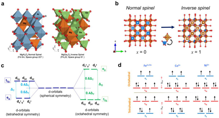
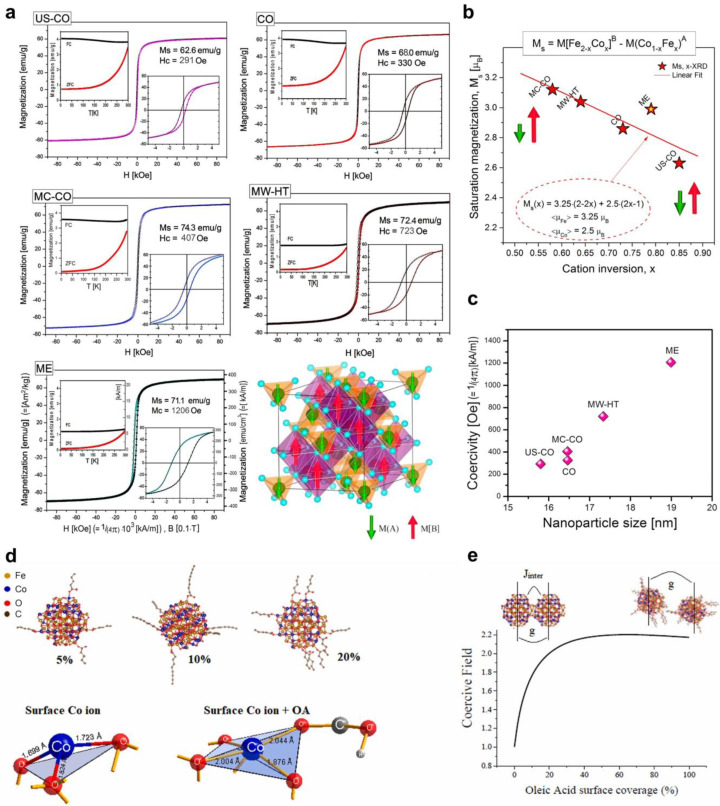
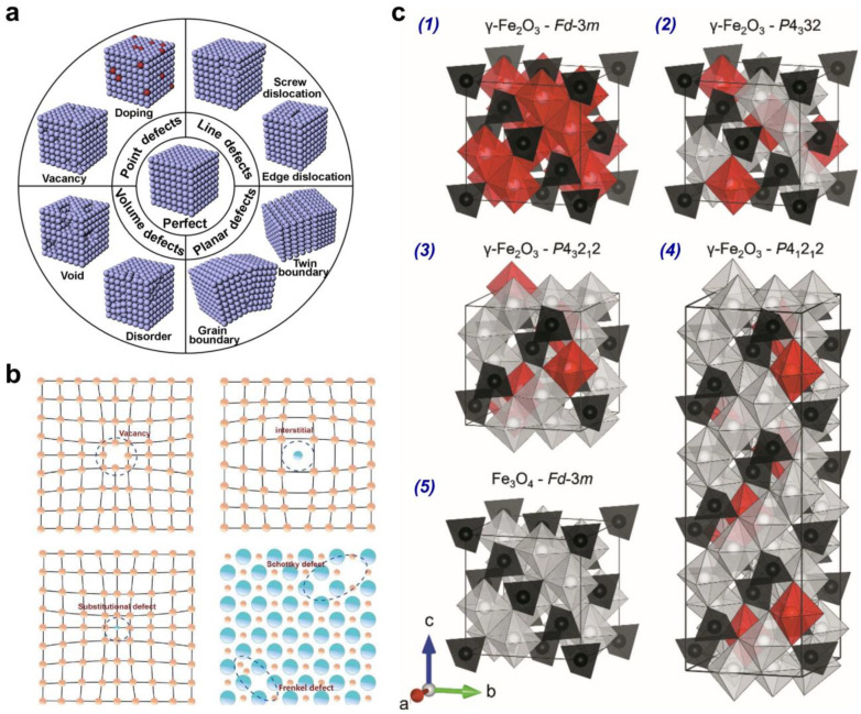
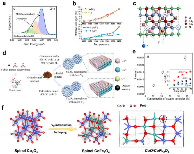
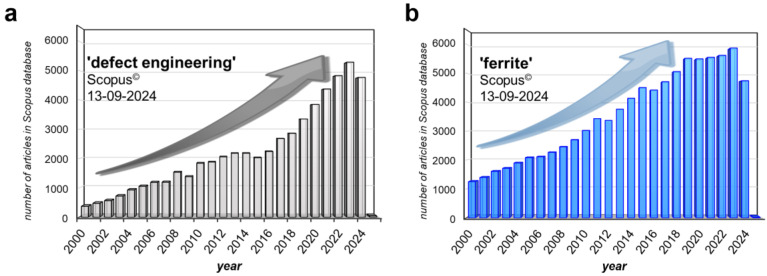
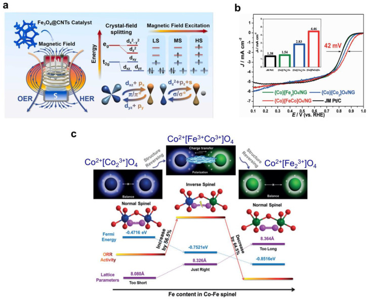
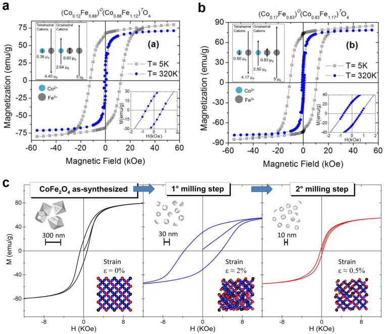
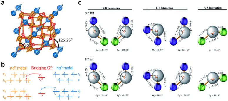
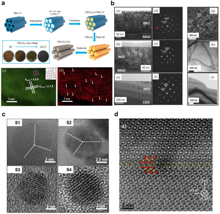
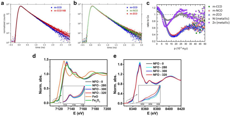
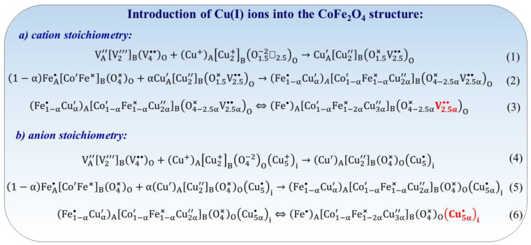
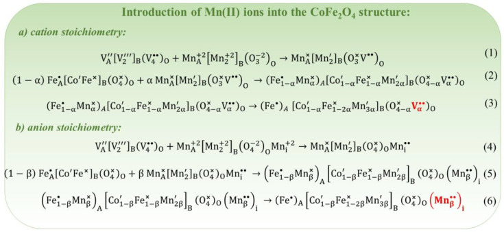
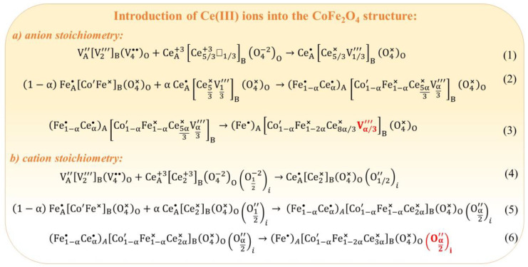
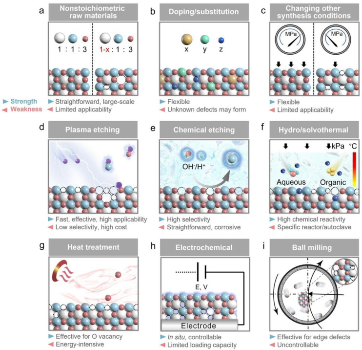
Spinel ferrites demonstrate extensive applications in different areas, like electrodes for electrochemical devices, gas sensors, catalysts, and magnetic adsorbents for environmentally important processes. However, defects in the real spinel structure can change the many physical and chemical properties of spinel ferrites. Although the number of defects in a crystal spinel lattice is small, their influence on the vast majority of physical properties could be really decisive. This review provides an overview of the structural characteristics of spinel compounds (e.g., CoFe2O4, NiFe2O4, ZnFe2O4, Fe3O4, γ-Fe2O3, Co3O4, Mn3O4, NiCo2O4, ZnCo2O4, Co2MnO4, etc.) and examines the influence of defects on their properties. Attention was paid to the classification (0D, 1D, 2D, and 3D defects), nomenclature, and the formation of point and surface defects in ferrites. An in-depth description of the defects responsible for the physicochemical properties and the methodologies employed for their determination are presented. DFT as the most common simulation approach is described in relation to modeling the point defects in spinel compounds. The significant influence of defect distribution on the magnetic interactions between cations, enhancing magnetic properties, is highlighted. The main defect-engineering strategies (direct synthesis and post-treatment) are described. An antistructural notation of active centers in spinel cobalt ferrite is presented. It is shown that the introduction of cations with different charges (e.g., Cu(I), Mn(II), Ce(III), or Ce(IV)) into the cobalt ferrite spinel matrix results in the formation of various point defects. The ability to predict the type of defects and their impact on material properties is the basis of defect engineering, which is currently an extremely promising direction in modern materials science.

Keywords: defect; ferrite; magnetism; spinel; structure; vacancy.


Conflict of interest statement

The author declares no conflicts of interest.

Figures

Figure 2
Figure 2
(a) Schematic illustration of the normal and inverse spinel structure (side view) (reprinted with permission from [38]. Copyright 2020 Springer Nature). (b) Top view of lattice cells of normal (left) and inverse (right) spinel ferrites (the oxygen ions are marked in red, Fe3+ ions are marked in orange, and M2+ ions are marked in blue) (reprinted with permission from [34]. Copyright 2021 American Chemical Society). (c) The d-orbitals splitting for the A- and B-cations in spinel sublattices. (d) The filling of the t2g and eg orbitals for the Fe, Co, and Ni cations (reprinted with permission from [15]. Copyright 2016 American Chemical Society).
Figure 6
Figure 6
(a) Saturation magnetizations, hysteresis loops, and ZFC/FC measurements of cobalt ferrite NPs obtained by various synthesis methods. The ferrimagnetic spinel structure is depicted in the right-bottom corner (reprinted with permission from [62]. Copyright 2024 MDPI). (b) The saturation magnetization vs. cation inversion (x) (reprinted with permission from [62]. Copyright 2024 MDPI). (c) Coercivity vs. CoFe2O4 NPs size (reprinted with permission from [62]. Copyright 2024 MDPI). (d) Relaxed structures of CoFe2O4 NPs covered with different amounts of oleic acid and the surface Co ions without covering and bonded with OA in the CoFe2O4 structure (reprinted from [65], Copyright (2023), with permission from Elsevier). (e) Coercivity vs. oleic acid surface coverage onto cobalt ferrite NPs (reprinted from [65], Copyright (2023), with permission from Elsevier).
Figure 8
Figure 8
(a) The common classification of defects (reprinted from [7], Copyright (2018), with permission from Elsevier). (b) The types of point defects: vacancy, interstitial defect, substitutional defect, Frenkel defect, and Schottky defect (reprinted from [89], Copyright (2020), with permission from Elsevier). (c) Illustrations of the possible structural configurations (1)–(4) in the γ-Fe2O3 and the structure of Fe3O4 (5) (black polyhedra are A-sites, white polyhedra are B-sites, red polyhedra are partially occupied or unoccupied B-sites) (reprinted from [81], Copyright (2021), with permission from International Union of Crystallography).
Figure 9
Figure 9
(a) The XPS spectra of O1s electrons in NiFe2O4−δ sintered at 1300 °C (reprinted from [92], Copyright (2022), with permission from Elsevier); (b) Trends in the area ratios of the VO, Fe2+, and Ni0 peaks with sintering temperature in XPS fitting results (reprinted from [92], Copyright (2022), with permission from Elsevier); (c) Mechanism of oxygen vacancy formation in nickel ferrite lattice due to oxygen deficiency (reprinted from [92], Copyright (2022), with permission from Elsevier); (d) Hydrothermal synthesis of Co3O4 catalyst with oxygen vacancies (reprinted from [113], Copyright (2020), with permission from Elsevier); (e) Relationship between the amount of VO and rate constant of PMS decomposition (reprinted from [113], Copyright (2020), with permission from Elsevier); (f) Scheme of the formation of defective CoO/CoFe2O4 material (dashed cycle is oxygen vacancy VO) (reprinted from [115], Copyright (2023), with permission from Elsevier).
Figure 1
Figure 1
The number of published papers from 2000 to 2024 using the keywords (a) “defect engineering” and (b) “ferrite” indexed in the Scopus database (as of 13 September 2024).
Figure 3
Figure 3
(a) The utilizing of the alternating magnetic field to induce the transition from ‘low-spin’ to ‘high-spin’ states in octahedral Fe ions in the Fe3O4@CNTs heterostructure (reprinted with permission from [40]. Copyright 2024 Elsevier). (b) The linear sweep voltammetry in an O2-saturated 0.1M KOH solution for {Co}[Fe2]O4/NG, {Co}[Co2]O4/NG, {Co}[FeCo]O4/NG, and Pt/C (reprinted with permission from ref. [41], copyright 2016 Wiley-VCH). (c) The dependence between the structure inversion and ORR activity for Co–Fe-based spinels (Fe green, Co blue, absorbed O magenta, lattice O red) (reprinted with permission from ref. [41], copyright 2016 Wiley).
Figure 4
Figure 4
(a,b) M–H hysteresis loops, obtained at 5 and 320 K, for CoFe2O4 NPs synthesized by the coprecipitation method and calcined at (a) 873 K and (b) 1073 K (the upper insets show a scheme of the magnetic ordering between the A- and B-cations) (reprinted from [58], Copyright (2020), with permission from Sociedad Mexicana de Física, A.C). (c) M–H hysteresis loops for cobalt ferrite obtained via two-step planetary milling treatment (the insets in the right bottom corner show the level of strain induced by milling) (reprinted from [59], Copyright (2017), with permission from Elsevier).
Figure 5
Figure 5
(a) The magnetic moments of the A-ions (blue) and the antiparallel magnetic moments of B-ions (orange) of MFe2O4 nanoparticles (M = Mn, Ni, and Zn) (reprinted with permission from [34]. Copyright 2021 American Chemical Society). (b) The scheme of super-exchange interaction, resulting in antiferromagnetic coupling of the B- (orange) and A- (blue) sites (reprinted with permission from [34]. Copyright 2021 American Chemical Society). (c) Configurations of ion pairs in spinel ferrites with favorable distances and angles for effective magnetic interactions in Co0.7Zn0.3GdxFe2−xO4 samples (reprinted with permission from [61]. Copyright 2018 The Royal Society of Chemistry).
Figure 7
Figure 7
(a) The possible main magnetic configurations and interactions between the neighboring cations from ordered normal spinel ZnFe2O4 (Case 1) to inverse magnetite spinel Fe3O4 (Case 6). Case 4 is an example of disordered ZnFe2O4 with the presence of an oxygen vacancy (OVac2−) (reprinted from [67], Copyright (2020), with permission from Wiley). (b) Local structure of ZnFe2O4 to explain the relaxation effect in the local environment of the oxygen vacancy (reprinted with permission from [71]. Copyright (2014) by the American Physical Society). (c,d) The isosurfaces and differences in (c) the charge density Δρ(r) and (d) the magnetization density Δm(r) around an oxygen vacancy (sphere with white cross) compared to the ideal structure (reprinted with permission from [71]. Copyright (2014) by the American Physical Society).
Figure 10
Figure 10
(a) A scheme of a one-step-impregnation hard-template method for obtaining mesoporous nickel ferrite. HAADF-STEM image of NiFe2O4 and live image simulated on GMS 3 software, with white arrows indicating oxygen vacancies in the NiFe2O4 structure (reprinted from [98], Copyright (2018), with permission from Elsevier). (b) TEM images and corresponding diffraction pattern taken for film/substrate for (a,d) MAO/NFO, (b,e) MGO/NFO, and (c,f) CGO/NFO thin films, respectively (separate spot shown by the red circle in (d) is due to strain relaxation); (g) diffraction contrast image of MAO/NFO shows the presence of APBs, whereas (h) MGO/NFO and (i) CGO/NFO do not show APBs defects (Copyright (2017) Wiley. Used with permission from [84]); (c) HRTEM images of cobalt ferrite NPs synthesized in the presence of different concentrations of 1,2-hexadecanediol as surfactant: S1 = 0 mM, S2 = 0.125 mM, S3 = 0.25 mM, and S4 = 0.5 mM (white dashed lines for S1 and S2 samples indicate crystallographic domain boundaries) (reprinted with permission from [119]. Copyright 2021 American Chemical Society); (d) HAADF-STEM image of the Fe3O4 with twin defect (outlined by yellow lines) with tetrahedral FeA sites in yellow and octahedral FeB sites in red (reprinted with permission from [120]. Copyright 2016 Springer Nature).
Figure 11
Figure 11
(a) Positron lifetime spectra for mesoporous CoCo2O4 and mesoporous NaBH4-treated CoCo2O4 samples (reprinted with permission from [99]. Copyright 2022 American Chemical Society). (b) Positron lifetime spectra for nontreated mesoporous samples: CoCo2O4, NiCo2O4, and ZnCo2O4 (reprinted with permission from [99]. Copyright 2022 American Chemical Society). (c) CDB ratio curves (related to pure metallic cobalt reference, dashed line) for nontreated CoCo2O4, NiCo2O4, and ZnCo2O4 samples (reprinted with permission from [99]. Copyright 2022 American Chemical Society). (d) Fe K-edge XANES spectra of mesoporous nickel ferrite (reprinted from [98], Copyright (2018), with permission from Elsevier). (e) Ni K-edge XANES spectra of mesoporous nickel ferrite (reprinted from [98], Copyright (2018), with permission from Elsevier).
Figure 12
Figure 12
The antistructure mechanism of Cu(I) ions introduction into the CoFe2O4 structure (⎕ is an anion (oxygen) vacancy).
Figure 13
Figure 13
The antistructure mechanism of Mn(II) ions introduction into the CoFe2O4 structure.
Figure 14
Figure 14
The antistructure mechanism of Ce(III) ions introduction into the CoFe2O4 structure (⎕ is an canion vacancy).
Figure 15
Figure 15
The antistructure mechanism of Ce(IV) ions introduction into the CoFe2O4 structure (⎕ is an canion vacancy).
Figure 16
Figure 16
The strength (blue triangles) and weakness (red triangles) of different strategies used in defect engineering: (a) non-stoichiometric ratio between the precursors, (b) doping/substitution, (c) changing-synthesis conditions, (d) plasma etching, (e) chemical etching, (f) hydrothermal/solvothermal treatment, (g) heat treatment, (h) electrochemical treatment, and (i) ball milling (reprinted with permission from [137]. Copyright 2022 American Chemical Society).

References

    1. Khan H., Naskar A., Bera S. 3—Vacancy and Defect Structures in Metal Oxides. In: Kumar V., Som S., Sharma V., Swart H.C.B.T.-M.O.D., editors. Metal Oxides. Elsevier; Amsterdam, The Netherlands: 2023. pp. 61–81.
    1. Gao S., Zhao S., Tang X., Sun L., Li Q., Yi H. Research on the Application of Defect Engineering in the Field of Environmental Catalysis. Green Energy Environ. 2024 doi: 10.1016/j.gee.2024.08.008. - DOI
    1. Li X., Wang J., Zhang S., Sun L., Zhang W., Dang F., Seifert H.J., Du Y. Intrinsic Defects in LiMn2O4: First-Principles Calculations. ACS Omega. 2021;6:21255–21264. doi: 10.1021/acsomega.1c01162. - DOI - PMC - PubMed
    1. Hamed Mashhadzadeh A., Salmankhani A., Zarghami Dehghani M., Spitas C., Saeb M.R. 9—Influence of Defects upon Mechanical Properties of Oxide Materials. In: Kumar V., Som S., Sharma V., Swart H.C., editors. Metal Oxides. Elsevier; Amsterdam, The Netherlands: 2023. pp. 253–280.
    1. Shluger A. In: Defects in Oxides in Electronic Devices BT—Handbook of Materials Modeling: Applications: Current and Emerging Materials. Andreoni W., Yip S., editors. Springer International Publishing; Cham, Germany: 2018. pp. 1–22.

LinkOut - more resources