. 2025 Jan;52(1):45-76.
doi: 10.1002/mp.17478. Epub 2024 Oct 25.

AAPM task group report 135.B: Quality assurance for robotic radiosurgery

Affiliations

AAPM task group report 135.B: Quality assurance for robotic radiosurgery

Lei Wang et al. Med Phys. 2025 Jan.

Abstract

AAPM Task Group Report 135.B covers new technology components that have been added to an established radiosurgery platform and updates the components that were not well covered in the previous report. Considering the current state of the platform, this task group (TG) is a combination of a foundational task group to establish the basis for new processes/technology and an educational task group updating guidelines on the established components of the platform. Because the technology discussed in this document has a relatively small user base compared to C-arm isocentric linacs, the authors chose to emphasize the educational components to assist medical physicists who are new to the technology and have not had the opportunity to receive in-depth vendor training at the time of reading this report. The TG has developed codes of practice, introduced QA, and developed guidelines which are generally expected to become enduring practice. This report makes prescriptive recommendations as there has not been enough longitudinal experience with some of the new technical components to develop a data-based risk analysis.

Keywords: image guided SBRT; image guided SRS; robotic radio‐surgery.


Conflict of interest statement

The Chair of the AAPM Task Group Report 135.B has reviewed the required Conflict of Interest statement on file or each member of AAPM Task Group Report 135.B and determined that disclosure of potential Conflicts of Interest is an adequate management plan.

The members of AAPM Task Group Report 135.B listed below attest that they have no potential Conflicts of Interest related to the subject matter or materials presented in this document: Lei Wang, Anand Prabhu, Ellen Wilcox, Jun Yang, Christoph Fuerweger, Jeffrey Garrett, David Taylor, Sonja Dieterich.

The members of AAPM Task Group Report 135.B listed below disclose the following potential Conflict(s) of Interest related to subject matter or materials presented in this document: Alan Cohen, Matt Noll, Martina Descovich.

Alan Cohen worked as a medical physicist at Accuray Inc. between November 2006 to June 2016. Matt Noll is currently the senior physics manager at Accuray Inc. Martina Descovich served as a member of the CyberKnife and Radixact clinical advisory boards in 2017–2018

Figures

FIGURE 1
FIGURE 1
Different configurations of the CK Xchange table: G4/VSI (a) with receptacle storage positions for the FCA, Iris, and M6/S7 (b) with receptacles for MLC, FCA, and Iris (from left to right). The M6/S7 Xchange table holds the 12 fixed cones on the side of the table and must be changed manually during treatment.
FIGURE 2
FIGURE 2
(a) Iris Collimator Segments—side view cross‐section showing segment geometry and collimated beam boundary. (b) Iris Lower Collimating Segment Bank—arrows show the direction of movement of each of the triangular cross‐section collimating segments. (c) Upper and Lower Iris Collimating segments as projected from the position of the radiation source. The inner dodecagon shape with variable line widths schematically represents the alternating beam penumbra widths produced at the treatment distance.
FIGURE 3
FIGURE 3
Sample Output Factors for Iris v2 and v3 as measured on two different CyberKnife systems. Error bars indicate the estimated range of measured values due to a change in field diameter by ±0.2 mm.
FIGURE 4
FIGURE 4
Birdcage with film holder for IQA (a), an example radiochromic film image of a 40 mm Iris field (b) and its optical density contours (c). The alternating two penumbra sizes can be seen around the field periphery.
FIGURE 5
FIGURE 5
Iris QA results (Stanford University) from a StereoChecker (Standard Imaging Inc.). The results are compared with one set of baseline measurements taken in April 2017. Standard deviations on the QA data for all 11 collimators are between 0.03 and 0.04 mm.
FIGURE 6
FIGURE 6
This figure displays the mechanical design of the second version, InCise 2, MLC: (a) illustration of the mechanical structure of the InCise 2 MLC, (b) three‐edged leaf end design, (c) an original video image from the secondary feedback camera, (d) the corrected secondary feedback image displayed with planned MLC and plan target overlaid.
FIGURE 7
FIGURE 7
(a) The MLC QA phantom is directly attached under the MLC. (b) The QA phantom with two Tungsten pins defining the center of the field and the Y axis. (c) The dose pattern of the garden fence film with the Tungsten markers identified and MLC template overlaid. (d) Analyzed results with tolerance of ±0.27 mm at 433.5 mm SAD.
FIGURE 8
FIGURE 8
Two years of monthly QA for an InCise 2 MLC using the film garden fence test (Stanford University) is shown. Mean deviations for the two leaf banks are displayed. Two tests were performed each month, one at head vertical position and one at head horizontal position with MLC travel vertical, either X1 on top or X2 on top.
FIGURE 9
FIGURE 9
An illustration of Synchrony treatment: (a) the skin movement R detected by the Synchrony camera in camera coordinates is used to predict the tumor position (X, Y, Z) in the patient. (b) A correlation model (linear model displayed) is established between the tumor location (X, Y, Z) and marker movement R.
FIGURE 10
FIGURE 10
Manufacturer provided Synchrony motion platform (a) and the motion phantom (b) for QA with fiducial tracking. A commercial lung phantom (c) with a rod attached to an actuator is used for Synchrony QA with Xsight Lung tracking. The rod holds the cube with a hidden target and orthogonal radiochromic films (d).
FIGURE 11
FIGURE 11
A lung tumor planned with Monte Carlo and 2‐view tracking (a), and the tumor as identified in the x‐ray images by the 2‐view tracking LOT (b). A lung tumor planned with Monte Carlo and 1‐view tracking (c), and the tumor as identified in one of the x‐ray images and tracked with 1‐view LOT (d).
FIGURE 12
FIGURE 12
Illustration of the 1‐view tracking concept. As the tumor moves through its motion trajectory (solid blue lines), the motion can be tracked from one camera view but not the other. The software generates an pITV for the untracked motion components (blue shaded areas).

Similar articles

Cited by

References

    1. Dieterich S, Cavedon C, Chuang CF, et al. Report of AAPM TG 135: quality assurance for robotic radiosurgery [published online ahead of print 2011/08/06]. Med Phys. 2011;38(6):2914‐2936. - PubMed
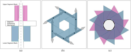
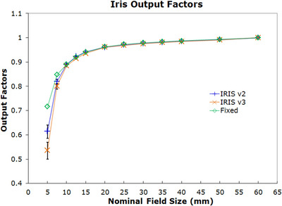
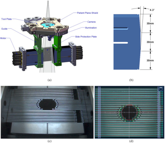
    1. Echner GG, Kilby W, Lee M, et al. The design, physical properties and clinical utility of an iris collimator for robotic radiosurgery [published online ahead of print 2009/08/19]. Phys Med Biol. 2009;54(18):5359‐5380. - PubMed
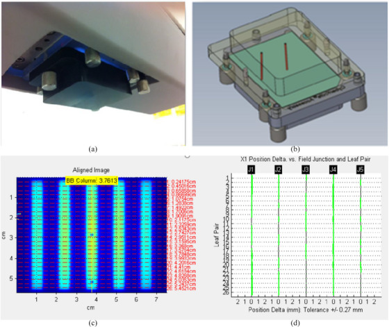
    1. Fürweger C, Prins P, Coskan H, Heijmen BJ. Characteristics and performance of the first commercial multileaf collimator for a robotic radiosurgery system. Med Phys. 2016;43(5):2063‐2071. - PubMed
    1. Asmerom G, Bourne D, Chappelow J, et al. The design and physical characterization of a multileaf collimator for robotic radiosurgery. Biomed Phys Eng Express. 2016;2(1):017003.
    1. Benjamin P, Fahimian LW. Introduction to CyberKnife® Technology. In: Steven D. Chang AV, eds. CyberKnife Stereotactic Radiosurgery. Nova Science Publishers, Inc.; 2014:1‐12.