

Monte Carlo modeling of the origin of contaminant electrons on a 0.5T bi-planar Linac-MR
- PMID: 39475282
- PMCID: PMC11788252
- DOI: 10.1002/mp.17495
Monte Carlo modeling of the origin of contaminant electrons on a 0.5T bi-planar Linac-MR
Abstract
Introduction: In the last decade, hybrid linear accelerator magnetic resonance imaging (Linac-MR) devices have evolved into FDA-cleared clinical tools, facilitating magnetic resonance guided radiotherapy (MRgRT). The addition of a magnetic field to radiation therapy has previously demonstrated dosimetric and electron effects regardless of magnetic field orientation.
Purpose: This study uses Monte Carlo simulations to investigate the importance and efficacy of the magnetic field design in mitigating surface dose enhancement in the Aurora-RT, focusing specifically on contaminant electrons, their origin, and energy spectrum.
Methods: The Aurora-RT 0.5 T Biplanar Linac-MR device was modeled using the BEAMnrc package using the updated EM macros, a magnetic field map generated from Opera 3D. Simulation generated phasespace data at the distal side of the first magnetic pole plate (89 cm) and at machine isocenter (120 cm) were analyzed with respect to electron energy spectra and electron creation origins, both with and without the static magnetic field.
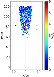
Results: The presence of the main magnetic field was verified to affect the origin and distribution of contaminant electrons, removing them from the air column up to 60 cm from the target, and focusing them along the CAX within the region below. Analysis of the remaining electron energy fluence reveals the net removal of electrons with energies > 2 MeV and generation of electrons with energies < 2 MeV in the presence of the static magnetic field as compared to no magnetic field. Moreover, in the presence of the magnetic field the integral energy contained in the contaminant electrons increases from 89 cm to isocenter but is still 15% less overall than the integral energy contained in contaminant electrons without the magnetic field.
Conclusion: This study provides an analysis of contaminant electrons in the Aurora-RT 0.5 T Linac-MR, emphasizing the role of magnetic field design in successfully minimizing electron contaminants.
Keywords: MR‐Linac; electron contamination; surface dose.
© 2024 The Author(s). Medical Physics published by Wiley Periodicals LLC on behalf of American Association of Physicists in Medicine.
Conflict of interest statement
B. Fallone is a co‐founder and chair of MagnetTx Oncology Solutions. No other authors report a conflict of interest.
Figures


References
-
- Fallone B, Carlone M, Murray B, et al. Development of a linac‐MRI system for real‐time ART. Med Phys. 2007;34:2547. doi:10.1118/1.2761342 - DOI
MeSH terms
LinkOut - more resources
Full Text Sources
Medical
