. 2024 Oct;634(8036):1096-1102.
doi: 10.1038/s41586-024-08077-6. Epub 2024 Oct 30.

Dynamic interface printing

Affiliations

Dynamic interface printing

Callum Vidler et al. Nature. 2024 Oct.

Abstract

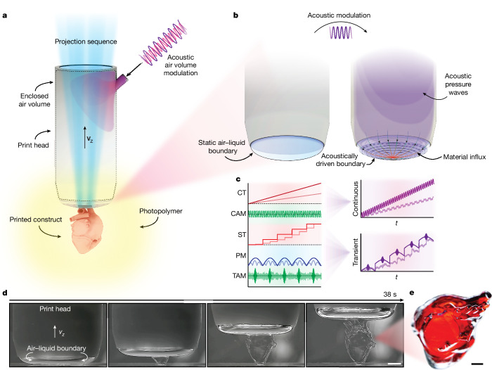
Additive manufacturing is an expanding multidisciplinary field encompassing applications including medical devices1, aerospace components2, microfabrication strategies3,4 and artificial organs5. Among additive manufacturing approaches, light-based printing technologies, including two-photon polymerization6, projection micro stereolithography7,8 and volumetric printing9-14, have garnered significant attention due to their speed, resolution or potential applications for biofabrication. Here we introduce dynamic interface printing, a new 3D printing approach that leverages an acoustically modulated, constrained air-liquid boundary to rapidly generate centimetre-scale 3D structures within tens of seconds. Unlike volumetric approaches, this process eliminates the need for intricate feedback systems, specialized chemistry or complex optics while maintaining rapid printing speeds. We demonstrate the versatility of this technique across a broad array of materials and intricate geometries, including those that would be impossible to print with conventional layer-by-layer methods. In doing so, we demonstrate the rapid fabrication of complex structures in situ, overprinting, structural parallelization and biofabrication utility. Moreover, we show that the formation of surface waves at the air-liquid boundary enables enhanced mass transport, improves material flexibility and permits 3D particle patterning. We, therefore, anticipate that this approach will be invaluable for applications where high-resolution, scalable throughput and biocompatible printing is required.


Conflict of interest statement

C.V., M.H. and D.J.C. have submitted Australian provisional patents (nos. 2023901976 and 2024900764) held/submitted by the University of Melbourne, which cover DIP of 3D structures.

Figures

Fig. 1
Fig. 1. Schematic illustration of DIP.
a, An air–liquid boundary forms at the base of a partially submerged print head. The boundary acts as a print interface in which patterned projections are used to locally solidify the photopolymer. b, Acoustic manipulation of the internal air volume in the print head promotes enhanced material influx through capillary-driven waves. c, In continuous mode (top right), the global location of the air–liquid interface(s) depends on continuous translation (CT) of the print head and constant acoustic modulation (CAM). In transient mode (bottom right), the location of the interface depends on stepped translation (ST), internal pressure modulation (PM) and transient acoustic modulation (TAM). d, Time-lapse photographs of the printing process for a heart geometry, demonstrating rapid fabrication of centimetre-scale constructs in less than 40 s. e, Printed heart geometry as shown in d, dyed red to improve visualization. Scale bars, 5 mm (d), 2 mm (e).
Fig. 2
Fig. 2. Characterization of the DIP system.
a, Images of the air–liquid interface profile formed at the base of the print head under the compressed, tangential and steady-state modes. Bézier curves were used to predict the shape of the interface during printing for each of the interface modes. b, The convex-slicing scheme was determined by first revolving the Bézier half-profile about the central axis and computing the voxel-wise intersection. c, Convex optimized projections extend in three dimensions and follow the boundary curvature for each interface mode. d, Print parameter space (n = 3) showing the optical power and print speed pairs for GelMA (blue), HDDA (red) and PEGDA (green). Inset, example of the rectangular test structure used to assess the parameter space. Scale bar, 2 mm. e, Accurate pixel area fraction for increasing print-head size for HDDA (red), GelMA (blue), PEGDA (green) and water (grey dashed). Left inset, variability of the area fraction for the 20 mm print head, dependent on material formulation. Right inset, simulated deviation of the pixel size based on Gaussian beam theory for a range of z values, compared to the Gaussian point spread function of the optical system, PSFGauss. a.u., arbitrary units. Source Data
Fig. 3
Fig. 3. Acoustic modulation in DIP.
a, Schematic illustration of the device used to acoustically modulate the air volume. b, Illustration of DIP with acoustic modulation. Capillary-gravity waves that form on the free surface of the print head result in flow fields that extend in three dimensions. c, Multi-coloured light is scattered from the air–liquid interface during acoustic excitation. d, PIV normal to the interface at 25 Hz for increasing amplitude. e, PIV perpendicular to the interface at 40 Hz and maximum amplitude, demonstrating the formation of high-velocity jetting flows. In d,e, the colour bars show average velocity (mm s1). f, Effect of acoustic actuation on material inflow below the interface for a 25 mm print head (f=50Hz,A=0.40). Inset, example time-series of a material inflow boundary during the wetting process. Coloured circles (blue to red) and black contours indicate the impending material boundary as a function of increasing time. g, Effect of acoustic stimulation on cellular sedimentation (n = 3). The cellular density (optical intensity, Ixz) is plotted over the height of a 10 mm circular pillar containing encapsulated 17 µm particles. Scale bars, 5 mm (c), 2.5 mm (e). Source Data
Fig. 4
Fig. 4. DIP capabilities.
a, Illustration of Bowman’s capsule and tri-helix model. b, Printed model of Bowman’s capsule showing the glomerulus. These were injected with red and blue dye. The print time was approximately 2 min. c, Tri-helix structure perfused with red and blue dye. d, Stitched top-down scanning electron microscope image of a Kelvin lattice printed with a 10 mm print head. Object field of view corresponds to a diameter of approximately 1.52Pxy for HDDA. e, Stitched top-down helium-ion microscopy image of an equal height micropillar array printed with HDDA. Some pillars were distorted by surface tension during drying due to the high aspect ratio of the structures. f, Comparison of the opacities of the PEGDA (transparent) and alginate (opaque) hydrogel materials when imaged against a standard US Air Force test target in a 10 mm cuvette. g, Top-down image of a tricuspid valve printed with an alginate bioink and corresponding micro computed tomography cross section (μCT). h, Print head with several independent air–liquid interfaces used to create a 3 × 3 array of the letters ‘DIP’. i, Three-dimensional patterning based on standing surface waves. Suspended particles were trapped in nodal locations depending on the driving frequency, as shown in segmented patterns A–C. The corresponding intensity profile of the image section is shown below each patterned region. j, Multiple-step overprinting of a ball-and-socket joint. k, Kidney-shaped model containing 7.2 million cells per millilitre printed in situ in a 12-well plate. l, Stitched and deconvolved fluorescence image of k after 24 h showing that high cell viability was maintained through the printing process. Scale bars, 100 µm (e), 1 mm (c,d), 2 mm (b,g,j,k,l), 4 mm (h). Source Data

References

    1. Bao, Y., Paunović, N. & Leroux, J. Challenges and opportunities in 3D printing of biodegradable medical devices by emerging photopolymerization techniques. Adv. Funct. Mater.32, 2109864 (2022).
    1. Martinez, D. W., Espino, M. T., Cascolan, H. M., Crisostomo, J. L. & Dizon, J. R. C. A comprehensive review on the application of 3D printing in the aerospace industry. Key Eng. Mater.913, 27–34 (2022).
    1. Lee, K.-S., Kim, R. H., Yang, D.-Y. & Park, S. H. Advances in 3D nano/microfabrication using two-photon initiated polymerization. Prog. Polym. Sci.33, 631–681 (2008).
    1. Zheng, X. et al. Design and optimization of a light-emitting diode projection micro-stereolithography three-dimensional manufacturing system. Rev. Sci. Instrum.83, 125001 (2012). - PubMed
    1. Lee, A. et al. 3D bioprinting of collagen to rebuild components of the human heart. Science365, 482–487 (2019). - PubMed

LinkOut - more resources