

Motion artifact variability in biomagnetic wearable devices
- PMID: 39483990
- PMCID: PMC11524837
- DOI: 10.3389/fmedt.2024.1457535
Motion artifact variability in biomagnetic wearable devices
Abstract
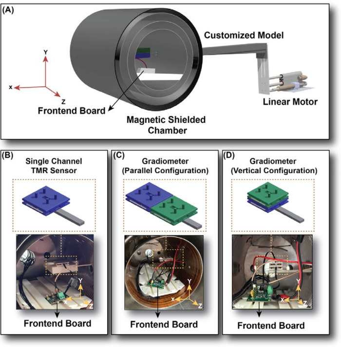
Motion artifacts can be a significant noise source in biomagnetic measurements when magnetic sensors are not separated from the signal source. In ambient environments, motion artifacts can be up to ten times stronger than the desired signals, varying with environmental conditions. This study evaluates the variability of these artifacts and the effectiveness of a gradiometer in reducing them in such settings. To achieve these objectives, we first measured the single channel output in varying magnetic field conditions to observe the effect of homogeneous and gradient background fields. Our analysis revealed that the variability in motion artifact within an ambient environment is primarily influenced by the gradient magnetic field rather than the homogeneous one. Subsequently, we configured a gradiometer in parallel and vertical alignment with the direction of vibration (X-axis). Our findings indicated that in a gradient background magnetic field ranging from 1 nT/mm to 10 nT/mm, the single-channel sensor output exhibited a change of 164.97 pT per mm unit increase, while the gradiometer output showed a change of only 0.75 pT/mm within the same range. Upon repositioning the gradiometer vertically (Y direction), perpendicular to the direction of vibration, the single-channel output slope increased to 196.85 pT, whereas the gradiometer output only increased by 1.06 pT/mm for the same range. Our findings highlight the influence of ambient environments on motion artifacts and demonstrate the potential of gradiometers to mitigate these effects. In the future, we plan to record biomagnetic signals both inside and outside the shielded room to compare the efficacy of different gradiometer designs under varying environmental conditions.
Keywords: biomagnetic measurements; gradient background field; homogeneous background field; motion artifacts; wearable sensors.
© 2024 Ghahremani Arekhloo, Wang, Parvizi, Tanwear, Zuo, McKinlay, Garcia Nuñez, Nazarpour and Heidari.
Conflict of interest statement
The authors declare that the research was conducted in the absence of any commercial or financial relationships that could be construed as a potential conflict of interest.
Figures


Similar articles
-
100 pT/cm single-point MEMS magnetic gradiometer from a commercial accelerometer.Microsyst Nanoeng. 2020 Aug 10;6:71. doi: 10.1038/s41378-020-0173-z. eCollection 2020. Microsyst Nanoeng. 2020. PMID: 34567681 Free PMC article.
-
Mean-square error due to gradiometer field measuring devices.IEEE Trans Biomed Eng. 1991 Jun;38(6):597-601. doi: 10.1109/10.81585. IEEE Trans Biomed Eng. 1991. PMID: 1879849
-
High Sensitivity Planar Hall Effect Magnetic Field Gradiometer for Measurements in Millimeter Scale Environments.Micromachines (Basel). 2022 Nov 2;13(11):1898. doi: 10.3390/mi13111898. Micromachines (Basel). 2022. PMID: 36363918 Free PMC article.
-
Recent Developments in Fabrication Methods and Measurement Schemes for Optically Pumped Magnetic Gradiometers: A Comprehensive Review.Micromachines (Basel). 2023 Dec 27;15(1):59. doi: 10.3390/mi15010059. Micromachines (Basel). 2023. PMID: 38258178 Free PMC article. Review.
-
Recognizing and Correcting MEG Artifacts.J Clin Neurophysiol. 2020 Nov;37(6):508-517. doi: 10.1097/WNP.0000000000000699. J Clin Neurophysiol. 2020. PMID: 33165224 Review.
Cited by
-
Medium density EMG armband for gesture recognition.Front Neurorobot. 2025 Apr 30;19:1531815. doi: 10.3389/fnbot.2025.1531815. eCollection 2025. Front Neurorobot. 2025. PMID: 40370635 Free PMC article.
References
-
- Arekhloo NG, Zuo S, Wang H, Imran M, Klotz T, Nazarpour K, et al. Investigating the volume conduction effect in MMG and EMG during action potential recording. 2022 29th IEEE International Conference on Electronics, Circuits and Systems (ICECS). IEEE; (2022).
-
- Williamson SJ, Kaufman L. Biomagnetism. J Magn Magn Mater. (1981) 22(2):129–201. 10.1016/0304-8853(81)90078-0 - DOI
LinkOut - more resources
Full Text Sources
Research Materials