. 2024 Dec;11(47):e2406977.
doi: 10.1002/advs.202406977. Epub 2024 Nov 5.

Drying of Soft Colloidal Films

Affiliations

Drying of Soft Colloidal Films

Keumkyung Kuk et al. Adv Sci (Weinh). 2024 Dec.

Abstract

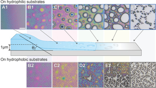
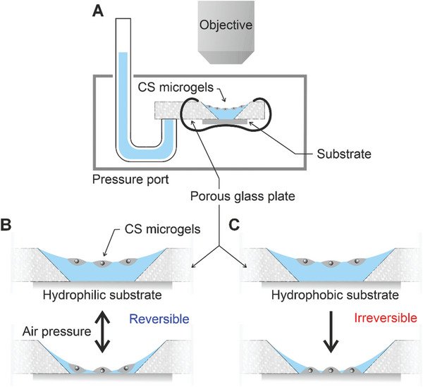
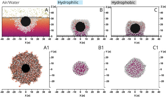
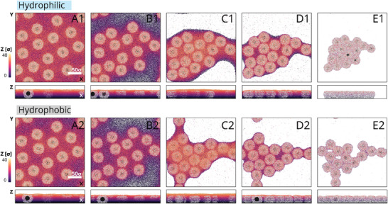
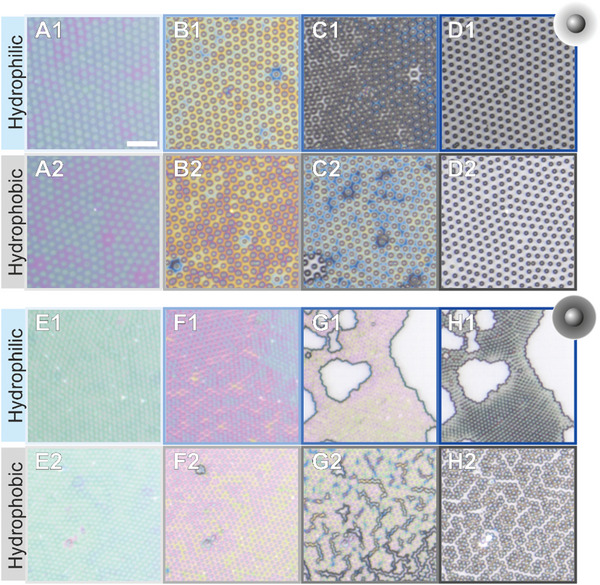
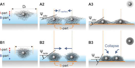
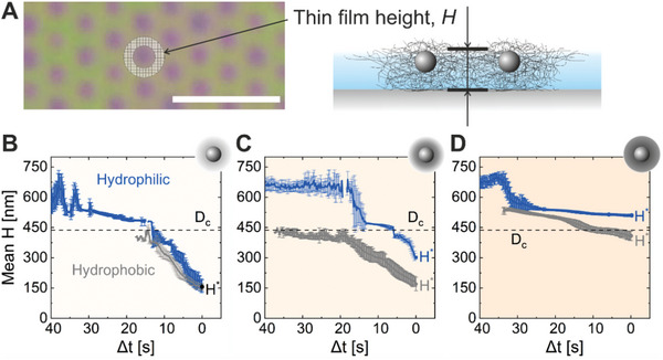
Thin films made of deformable micro- and nano-units, such as biological membranes, polymer interfaces, and particle-laden liquid surfaces, exhibit a complex behavior during drying, with consequences for various applications like wound healing, coating technologies, and additive manufacturing. Studying the drying dynamics and structural changes of soft colloidal films thus holds the potential to yield valuable insights to achieve improvements for applications. In this study, interfacial monolayers of core-shell (CS) microgels with varying degrees of softness are employed as model systems and to investigate their drying behavior on differently modified solid substrates (hydrophobic vs hydrophilic). By leveraging video microscopy, particle tracking, and thin film interference, this study shed light on the interplay between microgel adhesion to solid surfaces and the immersion capillary forces that arise in the thin liquid film. It is discovered that a dried replica of the interfacial microstructure can be more accurately achieved on a hydrophobic substrate relative to a hydrophilic one, particularly when employing softer colloids as opposed to harder counterparts. These observations are qualitatively supported by experiments with a thin film pressure balance which allows mimicking and controlling the drying process and by computer simulations with coarse-grained models.

Keywords: capillary forces; core‐shell microgels; fluid interface‐mediated colloidal assembly; microgel‐to‐substrate adhesion; thin film.


Conflict of interest statement

The authors declare no conflict of interest.

Figures

Figure 1
Figure 1
CS microgels with shells of different softness. Left: Schematic illustration of the structure of CS microgels with different crosslinker densities. The solid core (silica, illustrated by the grey sphere) is surrounded by crosslinked PNIPAM shells that are simplified by grey coronas. Dark and light coronas denote high and low crosslinking density, respectively. Right: Degree of lateral deformation at the air/water interface (Di/Dh). The microgels were adsorbed to interfaces from ethanolic and aqueous dispersion, with a 30‐min equilibration. The crosslinker density of the PNIPAM shells increases from top to bottom with the sketches representing the three different CS microgels (CS‐low, CS‐medium, and CS‐high).
Figure 2
Figure 2
Sketch illustrating the drying of microgel films (middle row) and reflected light microscopy images of CS‐medium films at mid‐Π (≈20 mN m−1) transferred onto hydrophilic (A1–F1) and hydrophobic substrates (B2–F2). The colors are due to thin film interference and will be later used to determine the local height. The scale bar corresponds to 5 µm. All microscopy images show the same magnification. θ is the receding wetting angle of the meniscus. Equal letters refer to similar film thicknesses deduced from similar colors.
Figure 3
Figure 3
Schematic illustrations of a modified thin film pressure balance (TFPB) setup (A) and the microgel‐laden interface oscillation experiment by pressure modulation using a hydrophilic substrate: far away from the solid substrate (B) and in the thin film on the substrate (C). Videos recorded for experiments on a film of CS‐medium are provided in the Supporting Information.
Figure 4
Figure 4
Snapshots of a selected CS microgel in the monolayer obtained at low Π before (A,A1) and after drying on hydrophilic (B,B1) and hydrophobic (C,C1) substrates. The upper row demonstrates a side view (cross‐section through the center of mass). The bottom row depicts thin layers of the microgels shown by dashed lines in the upper row, i.e., they are upper view (A1) and contact area on hydrophilic (B1) and hydrophobic (C1) substrates. The purple dots in (B,B1) and (C,C1) correspond to residual water.
Figure 5
Figure 5
Illustration (top views) of the different stages of microgel film obtained at low Π drying on hydrophilic (A1–E1) and hydrophobic (A2–E2) substrates as revealed by computer simulations. The narrow panels below the top views are the corresponding side views, i.e., cross‐sections of each panel along Z. The height of the film with residual water is depicted by the vertical color bar. White regions in the snapshots correspond to the bare substrate after water evaporation.
Figure 6
Figure 6
Reflected light microscopy images of CS‐low (A–D) and CS‐high microgel films (E–H) at mid‐Π (≈20 mN m−1) transferred onto hydrophilic (A1–D1, E1–H1) and hydrophobic substrates (A2–D2, E2–H2) during the drying process. The scale bar corresponds to 5 µm.
Figure 7
Figure 7
Scheme of forces acting on a small particle with a radius of R, immersed in a thin water film with a height of H0. The angles between the interfaces can be characterized by the particle contact angle, α, and the wetting angle ϕc. The particle is under the influence of forces that arise from the surface tension, Fσ, of the liquid along the wetted perimeter and the upward normal force exerted from the solid substrate, FN.
Figure 8
Figure 8
(A1,B1) Schematic illustration of microgels with a low (A1) and high crosslinker density (B1) at the air/water interface and their interfacial diameter, Di. (A2,B2) Upon drying, at the same Dc‐c and a given film height (Dh > H > Dc), softer microgels (A2) have a larger contact area to the substrate (highlighted in orange) and lower meniscus slope angle (Ψ) compared to harder microgels (B2). (A3,B3) Soft microgels are, therefore, more likely to stay in position (A3) than to collapse (B3).
Figure 9
Figure 9
Film height, H, shown in an exemplary frame (A, left) and in a sketch (A, right). The scale bar corresponds to 5 µm. Evolution of the height profiles of ten randomly chosen CS microgels in corresponding films drying on the hydrophilic (blue) and hydrophobic (grey) substrates for CS‐low (B), CS‐medium (C), and CS‐high (D). Δt represents the time difference, with 0 as the reference point, where H* is observed.

References

    1. Langevin D., Emulsions, Microemulsions and Foams, Soft and Biological Matter, Springer, Cham; 2020.
    1. Pickering S. U., J. Chem. Soc., Trans. 1907, 91, 2001.
    1. Dekker R. I., Velandia S. F., Kibbelaar H. V. M., Morcy A., Sadtler V., Roques‐Carmes T., Groenewold J., Kegel W. K., Velikov K. P., Bonn D., Soft Matter 2023, 19, 1941. - PubMed
    1. Binks B. P., Curr. Opin. Colloid Interface Sci. 2002, 7, 21.
    1. Zeng C., Faaborg M. W., Sherif A., Falk M. J., Hajian R., Xiao M., Hartig K., Bar‐Sinai Y., Brenner M. P., Manoharan V. N., Nature 2022, 611, 68. - PubMed