. 2024 Nov 12;121(46):e2412086121.
doi: 10.1073/pnas.2412086121. Epub 2024 Nov 7.

Sensory artificial cilia for in situ monitoring of airway physiological properties

Affiliations

Sensory artificial cilia for in situ monitoring of airway physiological properties

Yusheng Wang et al. Proc Natl Acad Sci U S A. .

Abstract

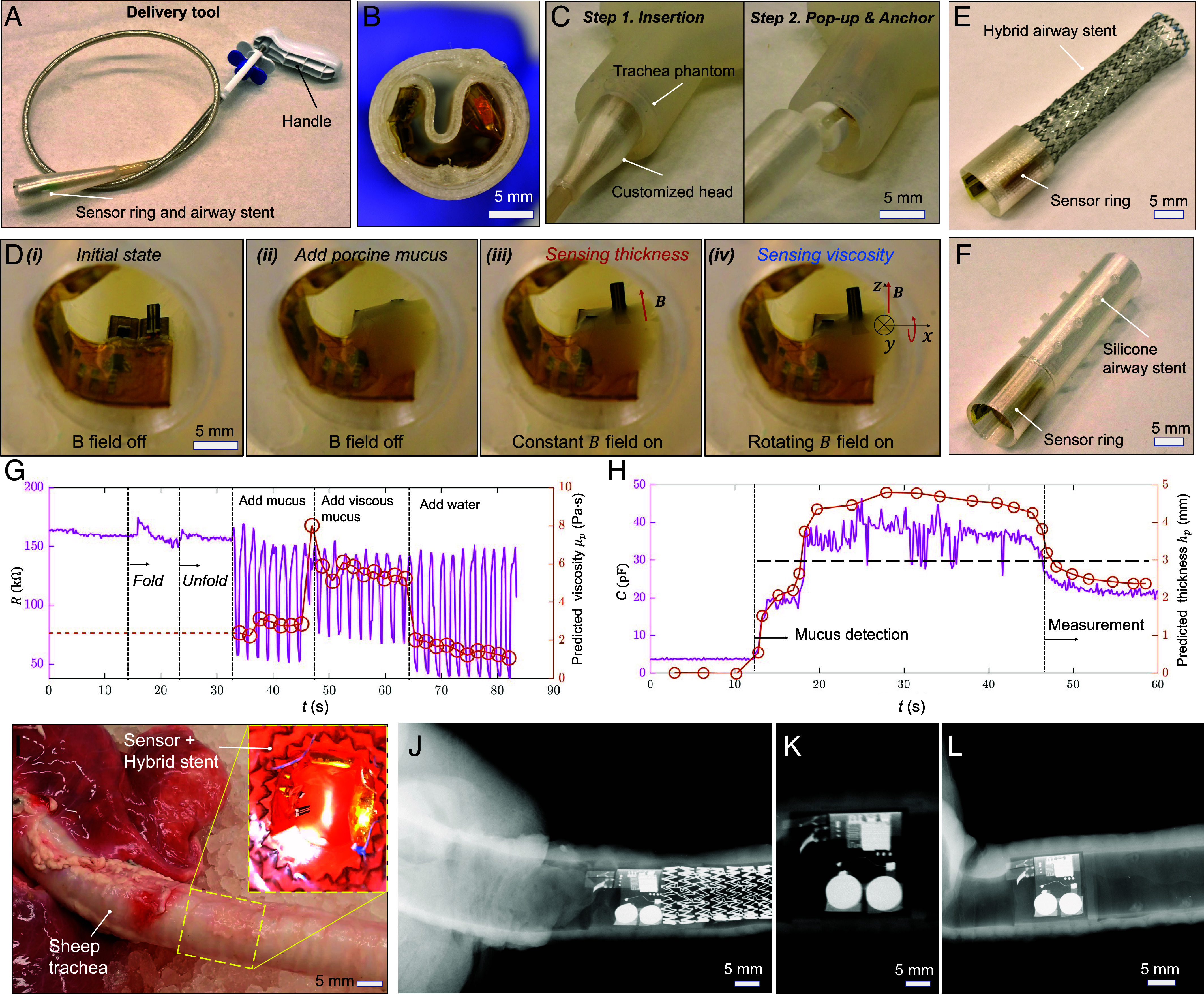
Continuously monitoring human airway conditions is crucial for timely interventions, especially when airway stents are implanted to alleviate central airway obstruction in lung cancer and other diseases. Mucus conditions, in particular, are important biomarkers for indicating inflammation and stent patency but remain challenging to monitor. Current methods, reliant on computational tomography imaging and bronchoscope inspection, pose risks due to radiation and lack the ability to provide continuous real-time feedback outside of hospitals. Inspired by the sensing ability of biological cilia, we report wireless sensing mechanisms in sensory artificial cilia for detecting mucus conditions, including viscosity and layer thickness, which are crucial biomarkers for disease severity. The sensing mechanism for mucus viscosity leverages external magnetic fields to actuate a magnetic artificial cilium and sense its shape using a flexible strain-gauge. Additionally, we report an artificial cilium with capacitance sensing for mucus layer thickness, offering unique self-calibration, adjustable sensitivity, and range, all enabled by external magnetic fields. To enable prolonged and wireless data access, we integrate Bluetooth Low Energy communication and onboard power, along with a wearable magnetic actuation system for sensor activation. We validate our method by deploying the sensor independently or in conjunction with an airway stent within a trachea phantom and sheep trachea ex vivo. The proposed sensing mechanisms and devices pave the way for real-time monitoring of mucus conditions, facilitating early disease detection and providing stent patency alerts, thereby allowing timely interventions and personalized care.

Keywords: airway stent; artificial cilia; lung; magnetic actuation; mucus sensing.


Conflict of interest statement

Competing interests statement:X.D. and Y.W. have a pending provisional patent.

Figures

Fig. 1.
Fig. 1.
Overview of the sensory artificial cilia for monitoring the conditions of airway stents and the airway. (A) Concept of the proposed device for monitoring airway mucus conditions inside a human trachea actuated by external magnetic fields. (B) Illustration of the viscosity and layer thickness sensors for sensing mucus properties. (C) Illustration of sensor signal outputs for liquids of different viscosities. (D) Illustration of the layer thickness sensor for sensing liquid layer thickness. (E) Illustration of system electronic components and connections. (F) Optical image of the electronic components of the sensory ring. The components include a BLE System-on-a-Chip, two coin-batteries, a viscosity sensor, a layer thickness sensor, and a magnetic sensor (with a temperature sensor inside). (G) Optical image of the electronic components of the sensory ring with a flexible backlayer made of Thermoplastic polyurethane (TPU). (H) The data flow chart of the electronic system and illustration of the user interface. (I) Optical image of a sensory ring and a hybrid airway stent integrated together for sensing mucus properties.
Fig. 2.
Fig. 2.
Design and calibration of the sensory artificial cilium for sensing liquid viscosity. (A) Optical images of the sensory artificial cilium for sensing liquid viscosity. (i) Overall dimension. (ii and iii) Zoomed-in optical images of the conductive material before coating (ii) and after coating (iii). (B) Schematics of the mechanism of sensing liquid viscosity. (i) Power stroke; (ii) Recovery stroke. (C) The resistance of the sensory artificial cilium and its curvature as a function of time when a rotating magnetic field is applied. (D) δR/R0 of the sensory artificial cilium as a function of time in liquids of different viscosities. (Scale bars, 100 micrometers.) δR=R-R0. R0: the resistance of the sensory artificial cilium when no magnetic field is applied. (E) The envelope of the time-varying sensor shapes in liquids of different viscosities (Movie S1). In D and E, magnetic field: f = 2 Hz, B = 20 mT. (F) δR/R0 of the viscosity sensor as a function of time in liquids of different viscosities. (G) The envelope of the time-varying sensor shapes in liquids of different viscosities (Movie S1). In F and G, magnetic field: f = 0.2 Hz, B = 20 mT. (H) A training dataset and a testing dataset based on measured viscosities and their corresponding peak-to-peak value of δR/R0 and f. B = 20 mT. Fitting method: Interpolation (Materials and Methods). (I) Peak-to-peak value of δR/R0 as a function of liquid viscosity at different f. (J) The predicted viscosities of liquids by the calibrated model in H as a function of their measured viscosities.
Fig. 3.
Fig. 3.
Characterization of the sensory artificial cilium for mucus viscosity sensing. (A) The measured liquid viscosity as a function of the viscosity sensor resistance ppδRR0 and the magnetic field frequency. (B) The predicted liquid viscosity by the viscosity sensor as a function of the measured liquid viscosity when rotating magnetic fields of different magnitudes are applied. Magnetic field: f = 0.2 Hz. Error: [0.03, 0.13, 0.02, 0.07, 0.32, 1.19] Pa·s. (C) The predicted liquid viscosity by the viscosity sensor as a function of the measured liquid viscosity when rotating magnetic fields in different rotating planes are applied. α is the angle between the rotating plane and the x-z plane. Magnetic field: f = 0.2 Hz, B = 20 mT. Error: [0.14, 0.13, 0.09, 0.27, 0.14, 1.01] Pa·s. (D) The predicted and measured liquid viscosities as a function of the shear rate. The liquid used is porcine mucus prepared by mixing mucin and water with a weight ratio of 1 by 7 and 1 by 8. ‘gt’ is short for ground truth. (E) The time-varying sensor resistance when diluting the mucus with water and heating up the mucus to lose water (Movie S1). (F) Optical images of the viscosity sensor inside mucus when sensing the time-varying mucus property.
Fig. 4.
Fig. 4.
Characterization of the sensory artificial cilium for liquid layer thickness sensing with reconfigurable sensitivity and range. (A) Optical image of the layer thickness sensor. (B) Optical image of a capacitor-based liquid layer thickness sensor when placed in porcine mucus. (C) The sensor capacitance as a function of mucus layer thickness. (D) The sensor capacitance as a function of the measured thickness of the porcine mucus when varying the mucin concentration in the porcine mucus. (E) Illustration of the calibration process. (i) Before submerging. (ii) Fully submerging. (iii) Measuring mucus thickness. k1=LcsinαcCmax-Cmin, h0=-LcsinαcCmax-CminCmin. (F) The sensor capacitance as a function of time during an online calibration process (Movie S2), dynamic viscosity: 3.5 Pa·s (weight ratio of mucin vs. water: 1 by 9). The calibration procedures include fully submerging the sensor for a maximum capacitor value, allowing the mucus to flow back, and sensing mucus thickness. (G) The measured mucus layer thickness as a function of time using the calibrated model. (H) The sensor capacitance as a function of the measured thickness when controlling the angle of the sensor by external magnetic fields. Magnetic field, B = 25 mT. (I) Optical images of the mucus layer thickness sensor at different tilting angles. (Scale bar, 3 mm.) In H and I, the coating polymer is Ecoflex 00-30.
Fig. 5.
Fig. 5.
Design and control of a wearable magnetic actuation system for sensory artificial cilia. (A) Digital rendering of the perspective view of a magnetic actuation system. The onboard magnet is rotationally, and translationally actuated by a DC motor and a servo-motor-slider-crank mechanism, respectively. Both actuation modes are controlled by the control electronics board, which is composed of a DC motor driver and a microcontroller. (B) Optical image of the wearable magnetic actuation system with onboard components mounted on a human chest model. (C) Illustration of the magnet relative to the longitudinal axis of a human trachea model and the characterized magnetic field Byz at different locations. (D) The time-varying magnetic field at a location with dz = 35 mm and dy = 0. (E) Optical image of the viscosity and layer thickness sensors bending or tilting when applying a rotating magnetic field. B = 25 mT. (F) Modulation of the magnitude and frequency of Byz by controlling the position and angular velocity of the onboard magnet.
Fig. 6.
Fig. 6.
Demonstration of the deployment and sensing function of the sensory artificial cilia inside a trachea phantom and a sheep trachea ex vivo. (A) Optical image of the delivery tool with a customized head for constraining the sensory ring. (B) Optical image of the sensory ring inside the head of the delivery tool. (C) Movie S4 frames of the delivery tool with the sensory ring embedded in the deployment process. (D) Movie S3 frames of the device deployed inside a trachea phantom. (i) No mucus. (ii) Add mucus, no actuation. (iii) Sensing mucus thickness, magnetically actuated. (iv) Sensing mucus viscosity, magnetically actuated. (E) Image of the hybrid stent integrated with the sensory ring. (F) Silicone airway stent integrated with the sensory ring. (G) Real-time viscosity sensor signal when varying the mucus viscosity. (H) Real-time mucus layer thickness sensor signal when varying the mucus layer thickness. When mucus layer thickness passes the threshold, alarm will be triggered for further intervention. (I) Optical image of the sensory ring with a hybrid stent delivered inside a sheep trachea. (JL) X-ray images of the sensory ring with a metal stent, only a sensory ring, and a sensory ring with a silicone stent inside a sheep trachea, respectively.

Similar articles

References

    1. Folch E., Keyes C., Airway stents. Ann. Cardiothorac. Surg. 7, 27383–27283 (2018). - PMC - PubMed
    1. Guibert N., Saka H., Dutau H., Airway stenting: Technological advancements and its role in interventional pulmonology. Respirology 25, 953–962 (2020). - PubMed
    1. Ernst A., Feller-Kopman D., Becker H. D., Mehta A. C., Central airway obstruction. Am. J. Respir Crit. Care Med. 169, 1278–1297 (2004). - PubMed
    1. Herlitz G. N., Sternberg D. I., Palazzo R., Arcasoy S., Sonett J. R., Treatment of bronchomalacia in cystic fibrosis by silicone stent. Ann. Thorac. Surg. 82, 2268–2270 (2006). - PubMed
    1. Bustamante-Marin X. M., Ostrowski L. E., Cilia and mucociliary clearance. Cold Spring Harb. Perspect. Biol. 9, a028241 (2017). - PMC - PubMed

LinkOut - more resources