. 2024 Oct 22;17(21):5146.
doi: 10.3390/ma17215146.

Enhanced Experimental Setup and Methodology for the Investigation of Corrosion Fatigue in Metallic Biodegradable Implant Materials

Affiliations

Enhanced Experimental Setup and Methodology for the Investigation of Corrosion Fatigue in Metallic Biodegradable Implant Materials

Lukas Schumacher et al. Materials (Basel). .

Abstract

Biodegradable implants as bone fixations may present a safe alternative to traditional permanent implants, reducing the risk of infections, promoting bone healing, and eliminating the need for removal surgeries. Structural integrity is an important consideration when choosing an implant material. As a biodegradable implant is being resorbed, until the natural bone has regrown, the implant material needs to provide mechanical stability. However, the corrosive environment of the human body may affect the fatigue life of the material. Conversely, mechanical stress can have an effect on electrochemical corrosion processes. This is known as corrosion fatigue. In the presented work, an experimental setup and methodology was established to analyze the corrosion fatigue of experimental bioresorbable materials while simultaneously monitoring the electrochemical processes. A double-walled measurement cell was constructed for a three-point bending test in Dulbecco's Phosphate-Buffered Saline (DPBS- -), which was used as simulated body fluid (SBF), at 37 ± 1 °C. The setup was combined with a three-electrode setup for corrosion measurements. Rod-shaped zinc samples were used to validate the setup's functionality. Preliminary static and dynamic bending tests were carried out as per the outlined methodology to determine the test parameters. Open-circuit as well as potentiostatic polarization measurements were performed with and without mechanical loading. For the control, fatigue tests were performed in an air environment. The tested zinc samples were inspected via scanning electron microscopy (SEM). Based on the measured mechanical and electrochemical values as well as the SEM images, the effects of the different environments were investigated, and the setup's functionality was verified. An analysis of the data showed that a comprehensive investigation of corrosion fatigue characteristics is feasible with the outlined approach. Therefore, this novel methodology shows great potential for furthering our understanding of the effects of corrosion on the fatigue of biodegradable implant materials.

Keywords: biodegradable implants; corrosion fatigue; experimental setup; open-circuit potential; potentiostatic polarization; three-point bending test; zinc.


Conflict of interest statement

The authors declare no conflicts of interest.

Figures

Figure 1
Figure 1
(A) Rough square zinc sample, 10 × 10 × 2 mm3; (B) rough zinc bending test sample, 27 × 3 × 2 mm3; (C) polished bending test sample after grinding; (D) electrical contacting with copper wire; (E) heat shrink tubing as insulation for soldering joint (blue: 0.8 mm and black: 1.6 mm).
Figure 2
Figure 2
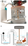
The experimental setup for investigating corrosion fatigue: (A) a photograph with labeling; (B) a schematic representation with labeling. A double-walled measurement cell mounted to the base plate of the dynamic testing machine. The working electrode (WE) and counter electrode (CE) are placed in the measurement cell filled with simulated body fluid (SBF) at 37 °C. The reference electrode (RE) is placed in a separate beaker filled with a KCl solution and connected by a salt bridge (SB) which is held in an additively manufactured holder.
Figure 3
Figure 3
Experimental setups 1, 2, and 3 using the three-electrode cell configuration consisting of an RE, WE, and CE. Setup 1 shows all electrodes in one cell, and setups 2 and 3 show the electrodes placed in two separate beakers connected by a KCl salt bridge. The Zn sample serves as the WE.
Figure 4
Figure 4
The flexural stress–flexural strain curve of the static three-point bending test for all five specimens. The force recorded by the machine is indicated on the second y-axis. The end of the linear area is marked in red at ~20 N.
Figure 5
Figure 5
A normalized deflection cycle diagram of dynamic loading. The failure limit for criterion (1) is marked in red at −1 mm. The measured maximum load amplitudes were 5 N (2 samples with (a) and (b)), 8.25 N (2 samples), 10 N (2 samples), 15 N (1 sample), and 20 N (1 sample).
Figure 6
Figure 6
Comparison of setups 1–3 and SB thickness: Current density–time diagram of PSP measurements with 8 mm (SB+) and 4 mm (SB−) salt bridges in setups 2 and 3. Setup 1 did not include SB. WE was polarized at 0.7 VAg/AgCl.
Figure 7
Figure 7
Comparison of deflection under mechanical stress in air and liquid (SBF): three control measurements in air (Air 1–3) and six measurements in liquid medium (M-OCP 1–3 and M-PSP 1-3). Loading force was set to 8.25 N, and loading duration was approx. 9.25 h. The red line marks a deflection of 0.00 mm.
Figure 8
Figure 8
Comparisons of the first 70 min of the OCPs of the purely electrochemical measurements (E-OCP 1–3) and mechanically loaded samples (M-OCP 1–3). The start of mechanical testing is marked by the respective arrows.
Figure 9
Figure 9
Minutes 5 to 25 of the M-OCP1 measurement showing the mechanical settling process. Once the OCP has stabilized for the first time, the mechanical stress starts at approx. 14 min.
Figure 10
Figure 10
The PSP of the bending test specimens over 9.25 h. The PSPs of the electrochemical control group (E-PSP 1–3) are compared with the PSPs under additional mechanical stress (M-PSP 1–3).
Figure 11
Figure 11
SEM images with most important findings of one used sample per group at 60× magnification: (A) Air1, (B) E-OCP1, (C) E-PSP1, (D) M-OCP1, and (E) M-PSP3.

References

    1. Paiva J.C.C., Oliveira L., Vaz M.F., Costa-de-Oliveira S. Biodegradable Bone Implants as a New Hope to Reduce Device-Associated Infections-A Systematic Review. Bioengineering. 2022;9:409. doi: 10.3390/bioengineering9080409. - DOI - PMC - PubMed
    1. Wang P., Gong Y., Zhou G., Ren W., Wang X. Biodegradable Implants for Internal Fixation of Fractures and Accelerated Bone Regeneration. ACS Omega. 2023;8:27920–27931. doi: 10.1021/acsomega.3c02727. - DOI - PMC - PubMed
    1. Arciola C.R., Campoccia D., Montanaro L. Implant infections: Adhesion, biofilm formation and immune evasion. Nat. Rev. Microbiol. 2018;16:397–409. doi: 10.1038/s41579-018-0019-y. - DOI - PubMed
    1. Magill S.S., Edwards J.R., Bamberg W., Beldavs Z.G., Dumyati G., Kainer M.A., Lynfield R., Maloney M., McAllister-Hollod L., Nadle J., et al. Multistate point-prevalence survey of health care-associated infections. N. Engl. J. Med. 2014;370:1198–1208. doi: 10.1056/NEJMoa1306801. - DOI - PMC - PubMed
    1. Jahr H., Li Y., Zhou J., Zadpoor A.A., Schröder K.-U. Additively Manufactured Absorbable Porous Metal Implants—Processing, Alloying and Corrosion Behavior. Front. Mater. 2021;8:628633. doi: 10.3389/fmats.2021.628633. - DOI

LinkOut - more resources