. 2025 Jan;22(1):187-192.
doi: 10.1038/s41592-024-02521-1. Epub 2024 Nov 11.

ONIX: a unified open-source platform for multimodal neural recording and perturbation during naturalistic behavior

Affiliations

ONIX: a unified open-source platform for multimodal neural recording and perturbation during naturalistic behavior

Jonathan P Newman et al. Nat Methods. 2025 Jan.

Abstract

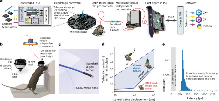
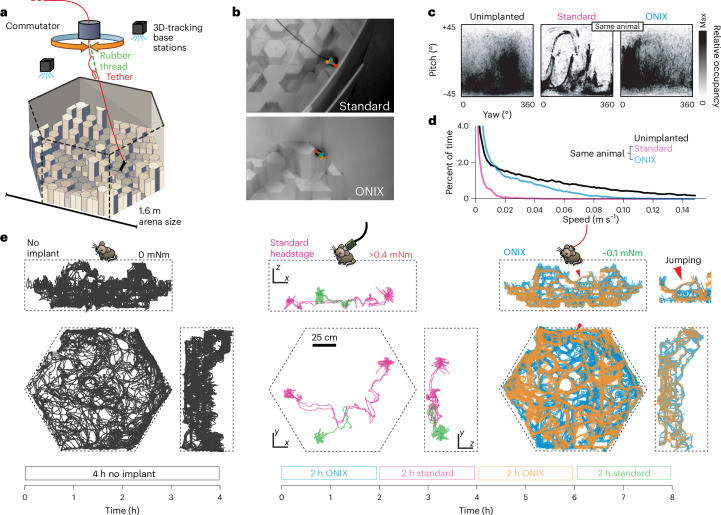
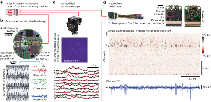
Behavioral neuroscience faces two conflicting demands: long-duration recordings from large neural populations and unimpeded animal behavior. To meet this challenge we developed ONIX, an open-source data acquisition system with high data throughput (2 GB s-1) and low closed-loop latencies (<1 ms) that uses a 0.3-mm thin tether to minimize behavioral impact. Head position and rotation are tracked in three dimensions and used to drive active commutation without torque measurements. ONIX can acquire data from combinations of passive electrodes, Neuropixels probes, head-mounted microscopes, cameras, three-dimensional trackers and other data sources. We performed uninterrupted, long (~7 h) neural recordings in mice as they traversed complex three-dimensional terrain, and multiday sleep-tracking recordings (~55 h). ONIX enabled exploration with similar mobility as nonimplanted animals, in contrast to conventional tethered systems, which have restricted movement. By combining long recordings with full mobility, our technology will enable progress on questions that require high-quality neural recordings during ethologically grounded behaviors.


Conflict of interest statement

Competing interests: J.P.N. is the president and J.V. and J.H.S. are board members of Open Ephys, a public benefit workers cooperative in Atlanta GA. F.C. is the founder of the Open Ephys Production Site in Lisbon Portugal. A.C.L. and F.C. are, and A.H.L was employed at the Open Ephys Production Site in Lisbon Portugal. G.L. is a director of NeuroGEARS. The other authors declare no competing interests.

Figures

Fig. 1
Fig. 1. ONIX, a unified open-source platform for unencumbered freely moving recordings.
a, Simplified block diagram of the ONI, illustrated via the tetrode headstage: multiple devices all communicate with the host PC over a single micro-coax cable via a serialization protocol, making it possible to design small multi-function headstages. b, The integrated nine-axis absolute orientation sensor and 3D tracking redundantly measure animal rotation, which drives the motorized commutator without the need to measure tether torque, enabling long recording durations. Small drive implants enable low-profile implants (~20 mm total height). c, The ONIX micro-coax, a 0.31 mm thin tether, compared to standard 12-wire digital tethers. d, Torque exerted on an animal’s head by tethers. Current tethers allow full mobility only in small arenas and in situations when the tether does not pull on the implant, while the ONIX micro-coax applies negligible torque. e, Performance of ONIX: with the 64-channel headstage, a 99.9% worst-case closed-loop latency, from neural voltage reading, to host PC, and back to the headstage (for example to trigger a light-emitting diode (LED)) of <1 ms can be achieved on Windows 10 (see also Extended Data Figs. 6 and 7). FPGA, field-programmable gate array; EIB, electrode interface board; FIFO, first-in first-out buffer.
Fig. 2
Fig. 2. Unrestricted naturalistic locomotion behavior with ONIX.
a, Overview of experiment. Mice were freely exploring a 3D arena made from Styrofoam pieces of varying heights. b, Unimplanted mice and mice with a standard tether (top) or ONIX micro-coax (bottom) were tracked in 3D using multicamera, markerless pose estimation. c, Head yaw and pitch occupancies over the course of a recording. d, Speed distributions over the course of a recording. e, Two-dimensional projection of mouse trajectories over the course of a recording session.
Fig. 3
Fig. 3. Stable long-term recordings during naturalistic locomotion.
a, Position of one 3D-tracking sensor on the headstage during a 7.3-h-long ONIX recording during which the mouse was free to explore the 3D arena. Red trace and excerpt show one of multiple instances of the mouse spontaneously jumping from a lower to a higher tile. b, Video frames of the jump (the tether is too thin to be visible at this magnification), see Supplementary Video 1. c, Raw voltages and spike peak amplitudes from two channels at hour 1 (top) and hour 7 (bottom) of the recording. d, 3D position, heading and smoothed firing rate of entire recording. e, Same data as in d, for excerpt around jump. f, z-position, raw voltage trace example and sorted spikes from 71 neurons during the jump.
Fig. 4
Fig. 4. ONIX is compatible with existing and future recording technologies.
a, ONIX, together with Bonsai, can simultaneously record from and synchronize multiple data sources, such as tetrode headstages, Neuropixels headstages and/or UCLA Miniscopes. b, 64-channel extracellular headstage, as used in Figs. 1–3, with 3D tracking, electrical stimulator (Extended Data Fig. 10), dual-channel LED driver and inertial measurement unit (IMU) (bottom side; not shown) (top). Example neural recording and corresponding 3D-pose traces collected from the headstage (bottom). c, ONIX is compatible with existing UCLA Miniscopes (v.3 and 4),. Maximum projection after background removal of an example recording in mouse CA1 (middle). Background-corrected fluorescence traces (black) and CNMF output (via Minian, red) of ten example neurons (bottom). d, An ONIX headstage for use with two Neuropixels probes and IMU to enable torque-free commutator use for long-term freely behaving recordings. A voltage heat map shows a segment from a head-fixed recording. A voltage time series from the channel indicated by the dotted line is shown in blue.
Extended Data Fig. 1
Extended Data Fig. 1. ONIX system block diagram.
a, The ONIX system architecture consists of 5 building blocks: (1) headstage firmware, (2) data serialization protocol, (3) host firmware, (4) host communication protocol, and (5) application programming interface (API). The firmware modules and host API (open black boxes) are both specified and implemented within this project. These are reusable across host hardware and physical interfaces (for example USB, ethernet, PCIe, etc). The serialization and host communication protocols (gray boxes) are generically specified by ONI. This project focuses on a micro-coaxial serializer to implement this spec. Other communication options would require custom, ONI-conforming firmware to be written. b, Each element of the architecture in panel (a) applied to the 64-channel Intan headstage used in Figs. 1–3. The serialization protocol and host communication protocol are implemented using a micro-coaxial serialization link and PCIe, respectively.
Extended Data Fig. 2
Extended Data Fig. 2. ONI communication block diagram.
Hubs (for example headstages, miniscopes, etc.) aggregate data and control sensors and actuators that interact with the world. Each sensor is provided with a separate, low-latency FIFO and control block. Configuration commands are demultiplexed from the host communication link to control each device on the headstage. Sensor data is multiplexed into a shared high-bandwidth link by a multiplexer on each hub. Low-bandwidth bidirectional configuration data is also transmitted over this link. In the hardware described in this paper, this link is implemented over a micro-coaxial serialization link, but could also be implemented using other wired or wireless links. Sensor data is demultiplexed by the host serial interface to create a local representation of the hub. This allows transparent control of each hub from the host computer, and low-level communication with the physical headstage via the serialized link is hidden by the firmware. Sensor and configuration data are streamed to and from the host PC using a high-speed bus, such as PCIe or USB3.0. The same API is used regardless of the physical communication interface. The appropriate drivers and translation layers are dynamically loaded for each physical interface that is used.
Extended Data Fig. 3
Extended Data Fig. 3. Relative weights and torque arms of comparable headstages.
Comparisons are between headstages on the same low-profile 16 tetrode drive implant. a, Current Intan-based headstage or comparable system. Omnetics connectors, vertical headstage layout, and tether all contribute to height and long moment arm, so that sideways forces on the tether exert strong rotational forces on the animal’s head. b, Best-possible low-profile headstage with current digital tethers, assuming a single, flat PCB design equivalent to the ONIX headstages described here. The digital tether still leads to a significant moment arm. c, In addition to a low-profile headstage, the ONIX micro-coax further lowers the torque arm, and also practically eliminates torque loads by virtue of an extremely light and flexible tether.
Extended Data Fig. 4
Extended Data Fig. 4. Precision of the 3D-tracking and 3D-pose measurements.
a, Experimental setup: A ONIX headstage was moved by known amounts at a 2-meter distance from the base stations. The base station pair was separated by 60 cm. b, Coordinates are derived from angular tracking data relative to the known base station positions. In our case (60 cm separation at a 2 m distance), this results in worse resolution in the height/Z direction than in the lateral/XY direction. c, Practically achievable absolute angular error of the BNO055 sensor on the headstages in dynamic environments without explicit calibration procedure. The absolute angle of a headstage was measured with an overhead camera, and the headstage was rotated randomly by hand in a non-optimized lab environment without any magnetic shielding. The ~2 degrees error range is consistent with the reported accuracy for the BNO055. d, Raw position measurements for known step displacements. e, Measurement jitter relative to known positions. In addition to the raw sample data, smoothed data at 15 Hz are plotted. f, Resulting cumulative distribution of absolute jitter. g-i, same as c-e but for height/Z measurements. The setup used here with large distance from the base stations and small distance between the base stations represents a worst-case scenario and demonstrates degraded Z resolution. Higher Z resolution can be achieved at the same distances by increasing the spacing between the base stations above 60 cm or decreasing the height of the base stations relative to the headstage.
Extended Data Fig. 5
Extended Data Fig. 5. Example setup and Bonsai workflow for simultaneous neural recording and behavior tracking.
a, A mouse with a Miniscope implant explores the same arena described in Figs. 2 and 3, and is being tracked by 4 side-mounted, and one overhead camera. The experiment is performed using the Bonsai software. In addition to the headstage connection (red), Bonsai controls the motorized commutator (blue) via a serial-over-USB link, as well as the 5 cameras (green) using the camera vendor API over USB. b, Mouse with a Miniscope v.4 implant, controlled by Bonsai via the ONIX system. c, The motorized commutator and 3D-tracking base stations. d, Excerpt of the Bonsai workflow: Data arrives via the’MiniscopeV4’ node (green), which communicates with a standard Miniscope through the ONIX micro-coax, is rescaled using an image processing nodes (blue) and saved to disk (yellow). A separate data path assigns time stamps to frames, synchronization with behavior cameras or other data. e, Bonsai workflow used to drive the commutator (Fig. 1). The head orientation quaternion output of the’MiniscopeV4 BNO55’ node (green) is one of the outputs of the BNO55 chip on the headstage (shared across the Miniscope, and the 64-channel Intan, as well as Neuropixel headstages). The quaternion is the saved to disk as raw data (purple), and sent to the ‘Commutator’ node (yellow), which drives the commutator to follow the animal’s rotation and remove any twisting of the tether. f, Example screenshot from Bonsai showing simultaneous data acquisition from all sources. Example workflows are available on the ONIX GitHub repository (https://open-ephys.github.io/onix-docs/Software%20Guide/Bonsai.ONIX/Bonsai%20Examples/index.html).
Extended Data Fig. 6
Extended Data Fig. 6. Host interface latency.
a, Latencies were measured for a closed-loop round-trip from the PCIe host to C software and back. b, Example theoretical data rate requirements for some high channel count recordings at 16 or 10 bit sample depth. Actual data rate requirements may differ depending on communication overhead. Future work could reduce the bandwidth requirements by compressing data on the headstage,. c, Different frequencies at which the closed-loop tests were run, each with increasing buffer sizes and resulting theoretical bandwidth. Note that the actual bandwidths can be limited by the headstage interconnect. d, Overview of latency ranges achievable with other technologies. e, Distribution of measured round-trip latency for all settings on a Windows 10 desktop computer with an Intel i5 CPU. The lowest latencies were measured with a 10 kHz rate. Results will differ on different hardware/OS, and depend on system load.
Extended Data Fig. 7
Extended Data Fig. 7. Real-world data rates of the ONIX system.
a, Overview of the system bandwidths. Bandwidth limits apply to different parts of the system: 1) The current serial over coax (Serializer-deserializer, SERDES) chip used on the headstages described here (Texas Instruments FPD-Link III for r 1-MP/60-fps), using a 100 MHz clock rate on a 12-bit interface, results in 1200Mbps (150MBps) bandwidth. The currently highest used bandwidth is ~48MBps on the Neuropixels headstage. Future implementation with other SERDES chips can improve this bandwidth, with the current headstage deserializers imposing a limit of ~300MBps. 2) The host interface currently runs an internal 64 bit bus at 250 MHz and is capable of 1.65GB/s. 3) Finally, the 4-lane PCIe interface used by ONIX is theoretically capable of ~2GB/s, of which we can currently use 1.65GB/s due to protocol overhead. It would be trivial to expand to higher lane counts in the future. b, To measure real-world throughput, the ONIX host has a load-testing FPGA-core with a configurable packet size and rate, which result in a given bandwidth. For a set of given transfer block sizes (here, powers of 2 starting at 64 bytes were used), we gradually increased the load bandwidth until the output FIFO, which is implemented on external RAM, started to fill, indicating that the transfer speed couldn’t cope with the data production. The resulting curve therefore corresponds to empirically achievable data rates. Measured bandwidth from data generated in a test device as a function of transfer block size. Yellow: Approximate data rate requirement for example numbers of electrophysiology channels, sampled at 30KHz and 16 bit with no optimization.
Extended Data Fig. 8
Extended Data Fig. 8. High-speed, high-acceleration behavior like jumping does not lead to large brain motion.
a, Excerpt from an experiment in which a mouse explored a 3D arena as described in the main experiment, with a Miniscope implant in dorsal Hippocampus. The 16 second excerpt shows the mouse jumping from one pillar onto a neighboring one at a distance of ~8.5 cm. We performed markerless tracking of the implant, and measured brain motion by computing the displacement of the Miniscope images using an fft-based image stabilization algorithm. b, Speed of the implant and brain motion for the excerpt. c, Speed of the implant shows no positive correlation with brain displacement.
Extended Data Fig. 9
Extended Data Fig. 9. Stable long-term electrophysiology without experimenter intervention.
a, A mouse was placed in a large home cage and electrophysiology from a laminar probe in prefrontal cortex was recorded for ~55 hours in a mouse holding room with an automated 12-hour light cycle without experimenter intervention. We observed no tangling or twisting of the recording tether. b, Neural data was post-processed in the same way as for the other experiments, and data from one channel was bandpass filtered in the 0.1-2, 6–10 and 30–50 Hz bands to compute spectral power across awake and sleep phases. Behavioral activity levels were quantified by smoothing the norm of the 3-dimensional acceleration vector from the headstage at 1 Hz. c, during sleep periods, a clear breathing rhythm could be observed in the IMU head angle data recorded on the headstage.
Extended Data Fig. 10
Extended Data Fig. 10. Integrated electrical microstimulation circuit on ONIX’s 64-channel Intan headstage.
a, example pulse train configuration via graphical user interface in Bonsai. b, Setup for characterizing the circuit: The stimulator was used to drive biphasic current pulses into a model load (47 nF capacitor in series with 10kOhm resistor to ground), representing a high impedance stimulation scenario. The voltage across the 10 kOhm resistor was measured with an oscilloscope to monitor the delivered current. Pulse trains consisted of 1 ms per phase, biphasic, positive first pulses with inter-pulse interval of 10 msec (83 Hz pulse to pulse period). c, Measurement results: the amplitude of both phases was varied from ±10 uA to ±1.5 mA. For pulse-based stimulation, each phase must satisfy the following inequality to be achievable with the system’s maximum voltage: |Istim* (Relectrode + tphase/Celectrode)| <= 15 V. In our test setup, for ±500 uA, this results in ~15.6 V per phase which is why voltage compliance was reached for this target current. If the compliance voltage is reached, or pulses are delivered with asymmetric positive and negative charges, a charge imbalance will occur, resulting in a residual electrode voltage following the conclusion of the stimulus. The large artifacts following such failed stimuli result from the onboard charge balancing circuit removing this voltage after each stimulation pulse concludes. The mild slopes on the successfully delivered pulses are due to the finite voltage slew rate of the stimulation circuit. The stimulus current is recorded though an auxiliary channel on the Intan chip for verification of stimulus current waveforms. d, Simplified electrical stimulation circuit. A DAC controls an improved Howland current pump. Electrodes are discharged in between pulses to reduce artifacts and impose charge balancing. Control signals provided by the headstage FPGA are shown to the left. Elements are referred to in the text using their labels.

Update of

References

    1. Niell, C. M. & Stryker, M. P. Modulation of visual responses by behavioral state in mouse visual cortex. Neuron65, 472–479 (2010). - PMC - PubMed
    1. Stringer, C. et al. Spontaneous behaviors drive multidimensional, brainwide activity. Science13, 255 (2019). - PMC - PubMed
    1. Rosenberg, M., Zhang, T., Perona, P. & Meister, M. Mice in a labyrinth exhibit rapid learning, sudden insight, and efficient exploration. eLife10, e66175 (2021). - PMC - PubMed
    1. Meister, M. Learning, fast and slow. Curr. Opin. Neurobiol.75, 102555 (2022). - PMC - PubMed
    1. Clemens, A. M., Wang, H. & Brecht, M. The lateral septum mediates kinship behavior in the rat. Nat. Commun.11, 3161 (2020). - PMC - PubMed

LinkOut - more resources