. 2024 Dec;17(4):NP298-NP318.
doi: 10.1177/19433875241272436. Epub 2024 Oct 24.

Guidelines for Orbital Defect Assessment and Patient-Specific Implant Design: Introducing OA2 (Orbital Assessment Algorithm)

Affiliations

Guidelines for Orbital Defect Assessment and Patient-Specific Implant Design: Introducing OA2 (Orbital Assessment Algorithm)

Nils-Claudius Gellrich et al. Craniomaxillofac Trauma Reconstr. 2024 Dec.

Abstract

Study design: This study presents a review of the evolutionary development in reconstructive orbital surgery over the past 3 decades. Additionally, it proposes the Orbital Assessment Algorithm (OA2) to enhance decision-making for intraorbital reconstruction of post-traumatic orbital deformities.

Objective: The objective of this paper is to provide insights into modern post-traumatic orbital reconstruction from a surgeon's perspective, with a specific focus on adult patients. It aims to highlight the advancements in computer-aided design and manufacturing techniques, particularly in the field of reconstructive orbital surgery, and to introduce the OA2 as a tool for improved decision-making in this context.

Methods: The study conducts a comprehensive review of the evolution of reconstructive orbital surgery, focusing on the integration of 3D technology into surgical practices. It also outlines the development and rationale behind the proposed OA2, emphasizing its potential to enhance the accuracy and efficacy of intraorbital reconstruction procedures for post-traumatic deformities.

Results: The review demonstrates the significant progress made in reconstructive orbital surgery, particularly in leveraging 3D technology for virtual modeling, navigation, and the design and manufacturing of patient-specific implants. The introduction of the OA2 provides a structured approach to assessing and addressing post-traumatic orbital deformities, offering potential benefits in decision-making and surgical outcomes.

Conclusions: In conclusion, this paper underscores the pivotal role of computer-aided design and manufacturing in advancing reconstructive orbital surgery. It highlights the importance of integrating innovative design concepts into implant manufacturing processes and emphasizes the potential of the OA2 to guide surgeons in the management of post-traumatic orbital deformities, ultimately contributing to improved patient outcomes.

Keywords: functionalized implant design; orbital assessment algorithm; orbital reconstruction; patient-specific implants; post-traumatic orbital defect; virtual modelling.


Conflict of interest statement

The author(s) declared the following potential conflicts of interest with respect to the research, authorship, and/or publication of this article: The authors received speakers honoraria from DePuys Synthes®, West Chester, PA, USA, Brainlab AG, Munich, Germany and KLS Martin Group, Tuttlingen, Germany.

Figures

Figure 1.
Figure 1.
Coronal view (Voxim®, IVS Solutions, Chemnitz, Germany); aligned dataset with a centered calibrated metric grid (1 box = 1 cm) for efficient measurement.
Figure 2.
Figure 2.
Visage® is a robust DICOM viewer, that efficiently allows data set alignment and identification of key features of a post-trauma volume dataset. The red line in the axial view showing the impressed medial orbital wall (A) is set to acquire the corresponding paramedian oblique sagittal view (B), where the whole length of the orbital floor is depressed (this proves that it is the post-traumatic defect which is the issue and not the fracture). The coronal view displays the down-fracture of the orbital floor including the transition zone to the medial wall, the inferior rectus muscle shows rounding (C). The 3D view (D) only serves as an overview, with dislocation of the left nasal bones.
Figure 3.
Figure 3.
Example of a clinical case with a post-traumatic right orbital defect, on which the OA2 is applied to check the below-mentioned ten key signs (Figures 6 and 7) using Visage®. The medial posterior bulge on the right side is missing (A); the anterior-posterior projection of the orbital floor shows a huge post-traumatic defect (B); the coronal view in hard (C) and soft-tissue (D) window shows the involvement of the orbital floor over the full width starting medially from the transition zone, which itself is in original position. Rounding of the inferior rectus muscle is demonstrated in (D). In such a case, a patient-specific implant helps to provide a safe post-traumatic orbital defect reconstruction.
Figure 4.
Figure 4.
Pointer-based navigation for position control during surgery (Elements®, Brainlab, Munich, Germany) with the digital object of the left patient-specific 2 wall orbital implant; in the upper row a multiplanar (axial, sagittal, coronal) and 3D-view show the pointer-tip at the key area at the beginning of the medial posterior bulge at the anterior part of the posterior third of the orbit.
Figure 5.
Figure 5.
Trajectory-based navigation for position control of the patient-specific implant (purple) during surgery (Elements®, Brainlab, Munich/Germany) of the same patient with the digital object of the left patient-specific 2 wall orbital implant; the left picture shows navigation of the medial (A) and the right picture of the lateral trajectory in 3D (B).
Figure 6.
Figure 6.
Superimposition of the virtual planning (purple) with the post-operative CT scan of the left orbit showing the adequate result of the implant position.
Figure 7.
Figure 7.
Three sagittal views in a CT scan of a right orbit demonstrate the extent of the post-traumatic orbital floor defect (23,8 mm) in the paramedian oblique sagittal view (A); a proposed implant design is displayed in the equivalent view (B); due to the flat designed posterior projection of the implant in red a correction is implemented by the surgeon for the engineer to change the implant design (C). The posterior projection of the implant was designed straight, i.e. without the preventive design feature of an “inverted snow shovel”; the final virtual orbital implant design is shown (D) in the en face 3D view (Materialise, Leuven, Belgium). (note: the final 3-D design significantly lacks important features, a modern 3D-printed orbital implant should have: implemented landmarks (trajectories, points), metric information on the implant, visible insertion control information on the implant).
Figure 8.
Figure 8.
Representative views and key signs (1-10) for orbital deformity analysis. The figure shows a summary of the schematic views of a left sided intact bony orbit in coronal, (paramedian oblique) sagittal and axial view; accordingly, the ten important key signs are marked, listed and implemented into the relevant views within the Orbital Assessment Algorithm (OA2). Axial view: The dashed line corresponds to the paramedian oblique vector - connecting the center of the inferior orbital rim and the entrance of the bony optic nerve canal (each marked with a large cross). Coronal view: The large cross marks the transition zone (1) between medial wall and orbital floor; the oval shape (10) symbolizes the regular intact shape of the inferior rectus muscle. Paramedian oblique sagittal view: the large cross marks the posterior ledge of the orbit.
Figure 9.
Figure 9.
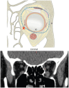
In the schematic coronal view the inferior rectus muscle (10) is rounded due to a post-traumatic deformity associated with breach of the periorbita; the muscle is rounded in a coronal view on a real patient helical CT scan (soft-tissue window) shown below.
Figure 10.
Figure 10.
Due to the atlas function implemented in Brainlab software, a fast algorithm-based segmentation is possible. The fully segmented 3D-data set is displayed for the 3D-, axial, sagittal and coronal view.
Figure 11.
Figure 11.
A virtually modelled orbit with thickened thin orbital walls can be exported as an STL-file and serve for a print-out biomodel with autoclavable resin, so that intra-operative individualized adaptation on top of the biomodel is feasible even with non-preformed or preformed orbital meshes (Brainlab, Munich, Germany).
Figure 12.
Figure 12.
Different orbital implants are displayed: non preformed fan-plate (A), with preshaping on a patient-specific biomodel (B); a preformed two-wall orbital plate (DePuys Synthes, West Chester, PA, USA) - based on statistical mean values of individuals - for the left orbital floor and medial orbital wall (C) and a first generation patient-specific orbital floor implant manufactured in SLM-technique (KLS Martin Group, Tuttlingen, Germany) (D).
Figure 13.
Figure 13.
Before the end of surgery, an intra-operative cone-beam CT was acquired and the dataset aligned; the orbital implant position is shown in coronal, axial and paramedian oblique sagittal view (A-C) (the same patient addressed in Figures 14–16). (Note: the implant lacks the “inverted snow shovel”-design at the posterior ledge in (C)).
Figure 14.
Figure 14.
Image fusion of 2 volume data sets from the same patient: paramedian oblique sagittal view pre- (A) and post-reconstruction (B) of a post-traumatic orbital floor defect. The post-traumatic orbital floor defect starts from the post-entry zone to the posterior ledge, i.e. the full length of the orbital floor is affected and depressed in the anterior to posterior projection. A non-preformed fan-plate (DePuys Synthes, West Chester, PA, USA) was manually shaped on a patient-specific biomodel for post-traumatic orbital defect reconstruction (note: other than SLM-manufactured patient-specific orbital implants these fan-plate based orbital implants might easily be deformed during the insertion process and they often show sharp edges see Figure 9A.
Figure 15.
Figure 15.
Comparison of the upper side of a patient-specific orbital implant in SLM-technique and a manually bent and shaped/cut fan-plate (A): the sharp edges and non-preventive-design of the fan-plate-based orbital implant is obvious. Other than the form-stable implants in (A) an original polydioxanone (PDS) foil is shown in (B), the shaped implant prior to insertion is shown in (C). (note: the important key areas cannot be adequately addressed in the implant design (C)).
Figure 16.
Figure 16.
State-of-the-art left large two-wall orbital implant with two navigationable lateral orbital wall extensions (implemented holes) and a lateral on top of the orbital rim-based fixation (KLS Martin Group, Tuttlingen, Germany). The shepherd´s crook shape to the medial orbital wall is intended for the volume correction need (A and B). The design of the orbital implant allows for self-centering in the dissected orbit. (A) biomodel helps the surgeon to have the physical plan of the orbital implant position and the corrected orbit (A); two implemented trajectories allow for navigational control of the correct implant position in the left orbit.
Figure 17.
Figure 17.
The implant inserted for the patient in Figure 7 via a retroseptal transconjunctival approach, where the incision is placed around 1 cm posterior to the lower eyelid margin (A); a brain or orbital retractor keeps the orbital tissues out of the field of vision (B); the patient-specific implant and an extra drill guide with a separate screw fixation to the inferior orbital rim are shown in (C) (Materialise, Leuven, Belgium); following insertion and single screw fixation on the inferior orbital rim the orbital implant is shown from above in (D).
Figure 18.
Figure 18.
3D and multiplanar view (screen capture) from the Curve® navigation system (Brainlab, Munich, Germany) during intra-operative pointer-based real time navigation (the same patient addressed in Figures 7 and 17).
Figure 19.
Figure 19.
Right paramedian oblique sagittal view of a post-traumatic secondary orbital deformity prior to reconstruction, after primary repair with PDS foil. The curved thick line shows the rough implant design with the post-entry zone (dip) and the “Lazy S”-shape levering on the posterior ledge area with the posterior margin of the implant pointed down.
Figure 20.
Figure 20.
For the patient in Figure 19 the aligned cone-beam CT dataset is shown in the coronal (A), paramedian oblique sagittal (B) and axial (C) view prior to secondary orbital reconstruction. (Note: the right orbital volume is significantly enlarged due to primary reconstruction elsewhere with a bioresorbable implant for the post-traumatic orbital floor defect; the outer frame with the zygoma and zygomatic arch is under corrected).
Figure 21.
Figure 21.
Post-operative cone-beam (A, B, D) and helical CT (C) planes show the post-traumatic orbital reconstruction due to the radiopacity of the patient-specific implant (A) in comparison to the unaffected orbital floor (B) in the paramedian oblique sagittal view; in addition to the implant three radiopaque spacers - made out of the same titanium grade V like the SLM-manufactured orbital implant - are shown to additionally downsize the orbital volume that has been even increased by for- and outwarding the impacted malar bone (C, D).
Figure 22.
Figure 22.
Two axial planes of a left corrected post-traumatic orbital defect are shown with a state-of-the-art patient-specific orbital implant recontouring the medial posterior bulge and the medial orbital wall (A and B); the paramedian oblique sagittal cone-beam CT slices show post-operatively, that the orbital implant is spanning the full sagittal projection of the orbital floor up to the posterior ledge (C); for comparison the equivalent right unaffected orbit is displayed (D).
Figure 23.
Figure 23.
Axial spiral CT slice showing an intact outer frame (A); the coronal views of the same patient show the hard tissue window (B) and the soft tissue window (C), where significant rounding of the inferior rectus muscle is obivous (with a flat, lentil shaped unharmed contralateral inferior rectus muscle on the right orbit) as a typical feature of significant orbital volume enlargement, resulting from rupture of the periorbita together with significant orbital floor displacement.
Figure 24.
Figure 24.
Intra-operatively acquired cone-beam CT with axial (A), coronal (B) views and adjustment for the paramedian oblique sagittal plane in the axial view (C) with the corresponding sagittal view (D) of the same patient from Figure 23. A perfect fit of the orbital implant reconstructing the full orbital floor is demonstrated, extended over the transition zone to the medial wall and seated with an extra extension to the lateral orbital wall.
Figure 25.
Figure 25.
Typical example of an inadequate primary repair of a post-traumatic left orbital defect with PDS foil and consecutive need for an iatrogenic secondary orbital reconstruction due to inappropriate orbital recontouring over time. Coronal view (A) and paramedian oblique sagittal view (B) showing the sagging of the orbital contents. (Note: these primarily inadequate treatments of extended post-traumatic orbital defects with bioresorbable materials predictably result in clinically relevant orbital deformities (enophthalmos, hypoglobus) requiring more complex secondary orbital reconstruction).
Figure 26.
Figure 26.
Coronal view of a secondary orbital reconstruction needed after midfacial fracture repair elsewhere including primary PDS-based reconstruction of the inner orbit (A). The large arrows highlight the enlargement of the left orbital volume. TZ marks the transition zone between medial wall and floor. A corresponding coronal view post-operatively is shown on the Brainlab platform (B) with a patient-specific orbital implant super-imposed onto the virtual planning (interrupted line). In addition, three simultaneously trapezoid spacers are shown: they were needed to allow for a balanced volume control in addition to the orbital implant and to correct globe dystopia: coming from an outwards gaze of the left eye luckily no further eye-muscle correction was needed, because regular stereoscopic vision was achieved after secondary orbital reconstruction.

Similar articles

Cited by

References

    1. Manson PN. The orbit after converse: seeing what is not there. J Craniofac Surg. 2004;15(3):363-367. doi:10.1097/00001665-200405000-00003 - DOI - PubMed
    1. Manson PN. Three-dimensional CT diagnosis of maxillofacial trauma. N Engl J Med. 1994;330(1):69. - PubMed
    1. Kolk A, Pautke C, Schott V, et al. Secondary post-traumatic enophthalmos: High-resolution magnetic resonance imaging compared with multislice computed tomography in postoperative orbital volume measurement. J Oral Maxillofac Surg. 2007;65(10):1926-1934. doi:10.1016/j.joms.2006.06.269 - DOI - PubMed
    1. Kokemueller H, Zizelmann C, Tavassol F, Paling T, Gellrich NC. A comprehensive approach to objective quantification of orbital dimensions. J Oral Maxillofac Surg. 2008;66(2):401-407. doi:10.1016/j.joms.2006.05.062 - DOI - PubMed
    1. Zimmerer RM, Ellis E, 3rd, Aniceto GS, et al. A prospective multicenter study to compare the precision of posttraumatic internal orbital reconstruction with standard preformed and individualized orbital implants. J Cranio-Maxillo-Fac Surg. 2016;44(9):1485-1497. doi:10.1016/j.jcms.2016.07.014 - DOI - PubMed

LinkOut - more resources