

Low capacitor stress reconfigurable quadratic boost converter with fault tolerant capability for rooftop solar PV application
- PMID: 39550526
- PMCID: PMC11569166
- DOI: 10.1038/s41598-024-79891-1
Low capacitor stress reconfigurable quadratic boost converter with fault tolerant capability for rooftop solar PV application
Abstract
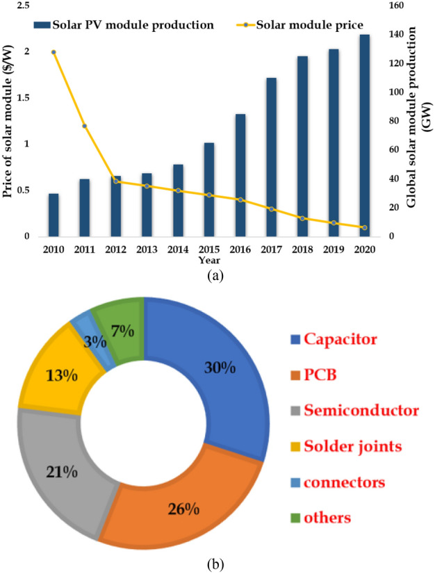
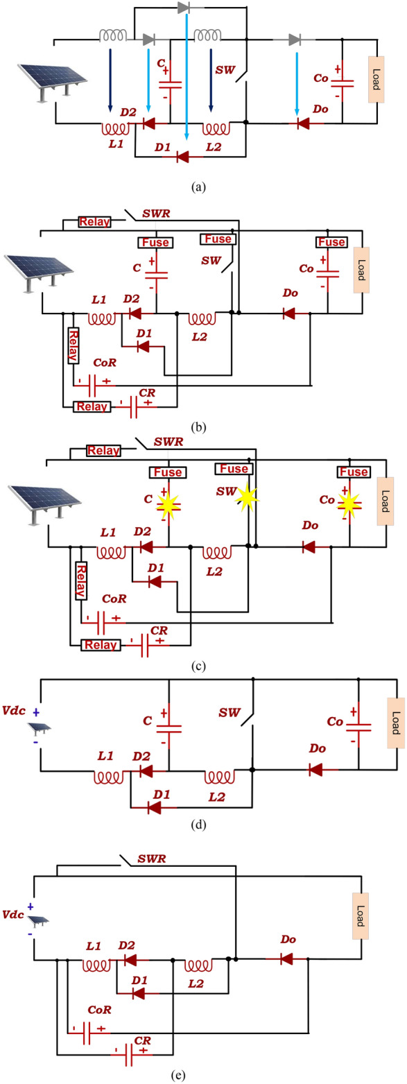
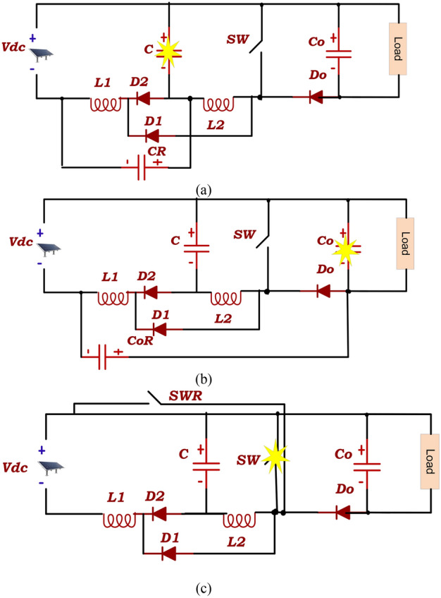
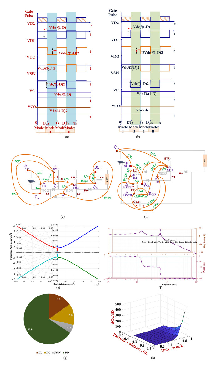
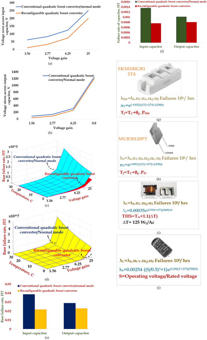
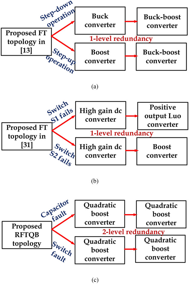
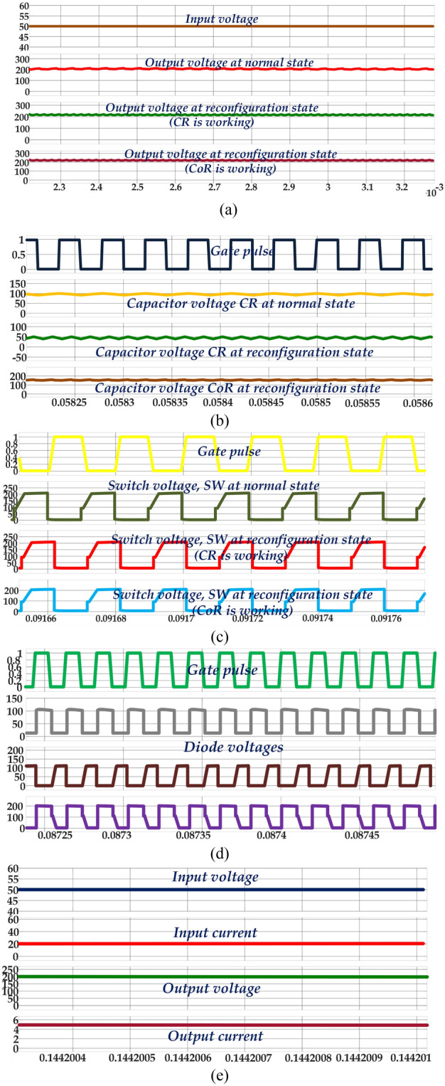
Recently, many high-gain topologies have been derived. However, there is a need for a high-gain converter with fault-tolerant features. In this paper, a fault-tolerant reconfigurable quadratic boost converter is proposed for DC microgrid application. In this novel topology, 2-level redundancy is achieved by addressing the fault in the switch and capacitors. The operation of the converter in normal operating conditions and reconfiguration mode is discussed. The derived topology can achieve the same voltage gain even in the reconfiguration mode. The proposed topology exhibits better performance in the reconfiguration state. The voltage stress across the input and output capacitor is reduced in that state. The reliability analysis of capacitors in both states is carried out and compared with the aid of the reliability handbook. Finally, the topology operation in a normal and reconfiguration state is validated by building a 1-kW hardware setup. The results show that the quadratic boost converter in a reconfiguration state operates without altering the voltage gain of the converter and with reduced voltage stress across the capacitors.
Keywords: Capacitor; Fault-tolerant; Quadratic and reliability; Reconfiguration; Switch.
© 2024. The Author(s).
Conflict of interest statement
Figures

References
-
- Kesavan, P. K., Subramaniam, U., Almakhles, D. J. & Selvam, S. Modelling and coordinated control of grid connected photovoltaic, wind turbine driven PMSG, and energy storage device for a hybrid DC/AC microgrid. Protect. Control Modern Power Syst.9 (1), 154–167. 10.23919/PCMP.2023.000272 (2024). - DOI
-
- Saafan, A. A., Khadkikar, V., Edpuganti, A., Moursi, M. S. E. & Zeineldin, H. H. A novel nonisolated four-port converter for flexible DC microgrid operation. IEEE Trans. Ind. Electron.71 (2), 1653–1664. 10.1109/TIE.2023.3257360 (2024). - DOI
-
- Wan, K., Zhao, J., Chen, Y. & Yu, M. A decentralized resilient control scheme for DC microgrids against faults on sensor and actuator. IEEE Trans. Circuits Syst. I Regul. Pap.71 (2), 816–827. 10.1109/TCSI.2023.3331881 (2024). - DOI
-
- Bhakar, P. S. & Kalaiselvi, J. Fault-tolerant and self-reliant characteristic in series resonant converter for semiconductor open/short-circuit faults. IEEE J. Emerg. Selected Top. Power Electron.11 (1), 1143–1153. 10.1109/JESTPE.2022.3161362 (2023). - DOI
-
- Mahafzah, K. A., Al-Shetwi, A. Q., Hannan, M. A., Babu, T. S. & Nwulu, N. A new Cuk-based DC-DC converter with improved efficiency and lower rated voltage of coupling capacitor. Sustainability15 (11), 8515 (2023). - DOI
LinkOut - more resources
Full Text Sources
