[Preprint]. 2024 Dec 11:2024.10.25.620262.
doi: 10.1101/2024.10.25.620262.

DNA nanodevice for analysis of force-activated protein extension and interactions

Affiliations

DNA nanodevice for analysis of force-activated protein extension and interactions

Kun Zhou et al. bioRxiv. .

Abstract

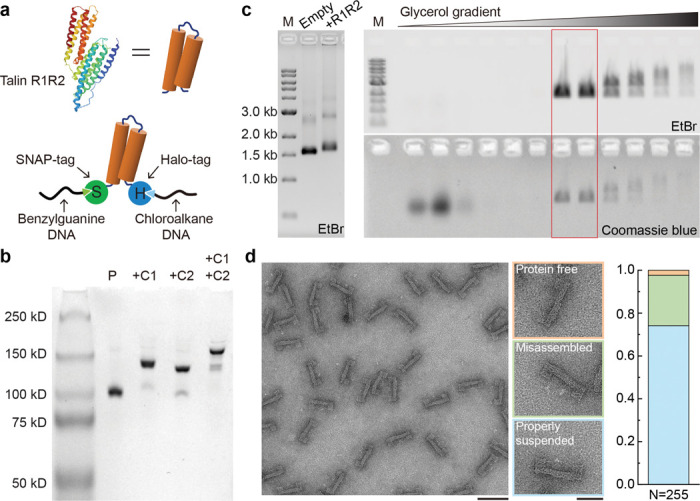
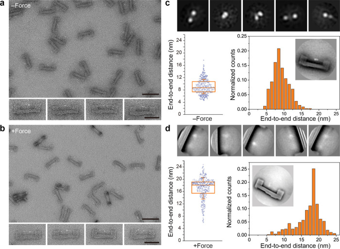
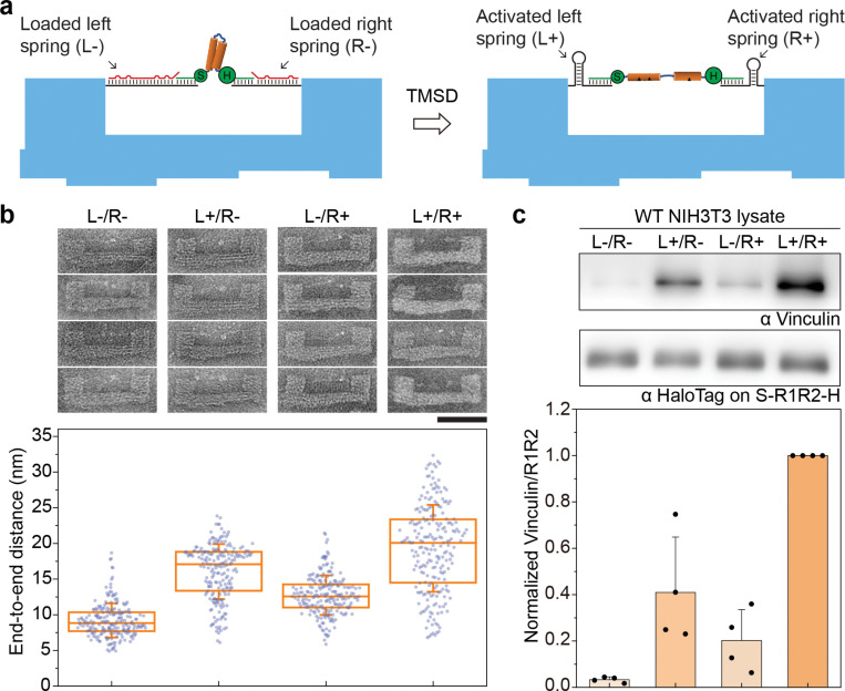
Force-induced changes in protein structure and function mediate cellular responses to mechanical stresses. Existing methods to study protein conformation under mechanical force are incompatible with biochemical and structural analysis. Taking advantage of DNA nanotechnology, including the well-defined geometry of DNA origami and programmable mechanics of DNA hairpins, we built a nanodevice to apply controlled forces to proteins. This device was used to study the R1-R2 segment of the talin1 rod domain as a model protein, which comprises two alpha-helical bundles that reversibly unfold under tension to expose binding sites for the cytoskeletal protein vinculin. Electron microscopy confirmed tension-dependent protein extension while biochemical analysis demonstrated enhanced vinculin binding under tension. The device could also be used in pull down assays with cell lysates, which identified filamins as novel tension-dependent talin binders. The DNA nanodevice is thus a valuable addition to the molecular toolbox for studying mechanosensitive proteins.


Figures

Figure 1.
Figure 1.. DNA origami device design, assembly and validation.
a) Schematics of the DNA origami nanomechanical device, which contains a U-shape frame (blue) and a pair of DNA handles with a gap for protein loading. A mechanosensitive protein (e.g., talin R1-R2, orange) can be mounted in the device through site-specifically conjugated DNA tethers (green curls). Controllable force can be generated by transforming an extended DNA handle (loaded spring) into a hairpin (activated spring) via toehold-mediated strand displacement (TMSD) that releases the target strand (red). b) A representative negative stain TEM image of the U-frame. Scale bar: 100 nm. Inset: a class average TEM image (120×120 nm2). c) Validation of force generation using a FRET-based DNA tension sensor (DNAts), a stem-loop structure (predicted unfolding force ≈ 8.3 pN at 25°C) labeled with Alexa Fluor 488 (AF488, green star) and Black Hole Quencher 1 (BHQ1, black circle). Top: schematic showing the TMSD reaction that releases the Cy5 (red star) labeled target strand to activate the DNA spring and unfold the DNAts. Bottom left: images of an agarose gel (upper: AF488 channel, lower: Cy5 channel) in which the DNA devices loaded with DNAts missing BHQ1 (Ctrl) and with complete DNAts before (-F) and 3 hr after (+F) TMSD were electrophoresed. Bottom right: trace of DNAts fluorescence during application of tension (upper, normalized to nuclease-treated DNAts), and the DNAts fluorescence quantified from the gel image (lower, normalized to DNAts without BHQ1). The bar graph shows mean and standard deviation.
Figure 2.
Figure 2.. Assembly of protein-loaded DNA-origami device.
a) Cartoon of the talin R1-R2 domain (PDB 1SJ8, top) and schematic of R1-R2 with terminal SNAP- and Halo-Tags (S-R1-R2-H) conjugated to benzylguanine- and chloroalkane-labeled DNA tethers (bottom). b) Native PAGE showing purified S-R1-R2-H (P), and DNA conjugated S-R1-R2-H hybridized to a 100-nt DNA strand complementary to the benzylguanine tether (+C1), to an 80-nt DNA strand complementary to the chloroalkane tether (+C2), or to both complementary strands (+C1 +C2). c) Left: agarose gel resolving the DNA origami device before (empty) and after (+R1R2) protein loading; right: agarose gel resolving fractions recovered from a glycerol gradient after rate-zonal centrifugation. Fractions in the red box are enriched in protein-loaded devices. M: 1kb DNA ladder; EtBr: ethidium bromide stain. d) Negative-stain electron micrographs of purified DNA-origami device after S-R1-R2-H loading. Among 255 devices analyzed, 2.4% are without a protein (orange group), 23.5% erroneously captured proteins (green group), and 74.1% contain a properly suspended protein (blue group). Scale bars: 100 nm for the zoomed-out image and 50 nm for zoomed-in images.
Figure 3.
Figure 3.. Tension induced conformational changes of S-R1-R2-H.
a) Negative-stain TEM images of purified DNA origami devices containing S-R1-R2-H. The initial gap for protein loading is 6 nm. The theoretical unfolding force of DNA spring is ~12.8 pN. Scale bars: 100 nm for zoomed-out image and 50 nm for zoomed-in images. b) Same as a, but after TMSD triggered force application. c) Single-particle analyses of S-R1-R2-H in the relaxed state. Top row: gallery of 2D class averages (30×30 nm2). Bottom row: distribution of distances measured between the two farthest domains of protein suspended within a DNA origami device (n = 361). The box and whisker plot shows the median, 25% and 75% percentiles, and standard deviation. Inset shows a class average (120×120 nm2) of the DNA device with relaxed S-R1-R2-H. d) Same as c, but after force induced protein unfolding. 2D class averages in the top row are 50×50 nm2. For the distance distribution, the number of devices measured is 483.
Figure 4.
Figure 4.. Force-dependent protein interactions with talin R1-R2.
a) Schematic of the pulldown assay. DNA origami devices, loaded with R1-R2, are immobilized on magnetic beads to assay force-activated protein binding. b) Western blot showing force-activated binding of VinD1-FLAG to R1-R2 as a function of gap size. A DNA hairpin with unfolding force (F1/2) of ~12.8 pN serves as spring. c) Western blot showing the effect of DNA spring design on force-activated VinD1-FLAG binding to R1-R2. An unstructured spring and two hairpin (HP) forming springs (F1/2≈ 8.8 and 12.8 pN), all 48-nt long, were tested. Initial gap = 6 nm. d) Tension-dependent R1-R2 binding proteins in cell lysates detected by mass spectrometry. Ratios of R1-R2 binders in the presence (+F) and absence (-F) of tension are plotted for the wildtype (WT, x-axis) and vinculin depleted (Vin−/−, y-axis) NIH3T3 cells. e) Western blot showing force-activated R1-R2 binding to vinculin in lysates of WT NIH3T3 cells. f) Western blots validating force-activated R1-R2 binding to FLNA in lysates of FLNA-GFP overexpressing cells (left) and purified FLNA-GFP (right). The ratios of talin binders to R1-R2 are normalized to the 6 nm gap, 12.8 pN HP, +F condition for each trial and plotted as bar graphs, which show means and standard deviations. Blank: DNA device without handle; 1-handle: defective device with R1-R2 tethered to only one handle; N.D.: not detected.
Figure 5.
Figure 5.. Programmable extension of talin R1-R2 led to varying vinculin binding.
a) Schematics showing an S-R1-R2-H extended by two springs (L and R) with different lengths and sequences on a DNA origami device. The R1-R2 domain, target strands, protein-conjugated DNA tethers, and DNA origami frame are depicted in orange, red, green, and blue, respectively. b) Representative TEM micrographs (top) and measured end-to-end distances (bottom) of S-R1-R2-H under relaxed (L-/R-) and various extended conditions (L+/R-, L-/R+, L+/R+) as the result of selective activation of the springs. The box and whisker plot shows the median, 25% and 75% percentiles, and standard deviation. Number of devices measured are 205, 208, 210 and 220. Scale bar: 50 nm. c) Western blot characterization of vinculin binding by relaxed and extended R1-R2 in cell lysates. The ratio of vinculin to R1-R2 is normalized to the maximally extended (L+/R+) condition for each trial and plotted as bar graphs, which show means and standard deviations.

Similar articles

References

    1. Mierke C. T. Extracellular Matrix Cues Regulate Mechanosensing and Mechanotransduction of Cancer Cells. Cells 13 (2024). 10.3390/cells13010096 - DOI - PMC - PubMed
    1. Orr A. W., Helmke B. P., Blackman B. R. & Schwartz M. A. Mechanisms of mechanotransduction. Dev Cell 10, 11–20 (2006). 10.1016/j.devcel.2005.12.006 - DOI - PubMed
    1. Hoffman B. D., Grashoff C. & Schwartz M. A. Dynamic molecular processes mediate cellular mechanotransduction. Nature 475, 316–323 (2011). 10.1038/nature10316 - DOI - PMC - PubMed
    1. Jin P., Jan L. Y. & Jan Y. N. Mechanosensitive Ion Channels: Structural Features Relevant to Mechanotransduction Mechanisms. Annu Rev Neurosci 43, 207–229 (2020). 10.1146/annurev-neuro-070918-050509 - DOI - PubMed
    1. Romani P., Valcarcel-Jimenez L., Frezza C. & Dupont S. Crosstalk between mechanotransduction and metabolism. Nat Rev Mol Cell Biol 22, 22–38 (2021). 10.1038/s41580-020-00306-w - DOI - PubMed

Publication types

LinkOut - more resources