. 2025 Aug;33(8):2833-2846.
doi: 10.1002/ksa.12539. Epub 2024 Nov 18.

Adapting the Dejour classification of trochlear dysplasia from qualitative radiograph- and CT-based assessments to quantitative MRI-based measurements

Collaborators, Affiliations

Adapting the Dejour classification of trochlear dysplasia from qualitative radiograph- and CT-based assessments to quantitative MRI-based measurements

David H Dejour et al. Knee Surg Sports Traumatol Arthrosc. 2025 Aug.

Abstract

Purpose: To adapt the current D. Dejour trochlear dysplasia classification (v2.0) to only rely on quantitative magnetic resonance imaging (MRI) measurements (v3.0) to maximize objectivity and repeatability.

Methods: A consecutive series of adult knee MRIs were divided into objective patellar instability (OPI, n = 127) or controls (n = 103; isolated meniscal tears) and postprocessed with multiplanar reconstruction (MPR) to standardize the sagittal plane and ensure true lateral views. Thresholds for sulcus angle, lateral trochlear inclination (LTI) and central bump were established using regression tree models to distinguish OPI from controls. The sensitivity and specificity of sulcus angle and LTI combinations to diagnose OPI were then evaluated, and the combination yielding the highest sensitivity was selected as basis for trochlear dysplasia classification. Finally, sulcus angle and LTI measurability and presence of a central bump >5 mm were used to grade dysplasia as low, moderate or high.

Results: The regression tree models produced thresholds of ≥157° for sulcus angle and <14° for LTI to distinguish OPI from controls. 'Sulcus angle ≥157° OR LTI < 14°' yielded the highest sensitivity (87%) to diagnose OPI. The quantitative MRI classification was sulcus angle <157° AND LTI ≥ 14° for Type 0 (No dysplasia); (sulcus angle ≥ 157° OR LTI < 14°) AND central bump <5 mm for Type 1 (Low-grade dysplasia); (sulcus angle OR LTI are 'unmeasurable') AND central bump <5 mm for Type 2 (Moderate-grade dysplasia); (sulcus angle ≥ 157° OR 'unmeasurable' OR LTI < 14° OR 'unmeasurable') AND central bump ≥5 mm for Type 3 (High-grade dysplasia).

Conclusion: This MRI classification depends exclusively on quantitative measurements, has excellent interobserver agreement, and yields high sensitivity to diagnose OPI. The MRI imaging protocol with MPR mode and standardized measurements could be quickly adopted and correctly applied by clinicians worldwide in any type of institution to determine the ideal treatment plan.

Level of evidence: Level III.

Keywords: bump; lateral trochlear inclination; magnetic resonance imaging; objective patellar instability; sulcus angle; trochlear dysplasia.


Conflict of interest statement

D. D. reports personal fees from SBM, outside the submitted work. The remaining authors declare no conflict of interest.

Figures

Figure 1
Figure 1
Flowchart of the study cohort of knees in the objective patellar instability (OPI) and control groups.
Figure 2
Figure 2
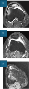
Identifying the posterior bicondylar line (PBCL). The PBCL is defined in three steps. (a) Step 1: Select the axial magnetic resonance imaging (MRI) slice that crosses the centre of the medial condyle. (b) Step 2: Select the sagittal MRI slice that crosses the most posterior point of the medial condyle. (c) Step 3: Return to the axial slice and draw the PBCL, which passes through the subchondral bone at the posterior aspect of the medial and lateral femoral condyles.
Figure 3
Figure 3
Description of trochlear shape as concave, flat or convex. Start by scrolling from cranial to caudal, select the first axial slice with the trochlear cartilage visible and showing or covering at least the entire lateral facet. The trochlear shape is described according to the cartilage contour as (a) Concave: trochlea with a sulcus, as well as medial and lateral facets. (b) Flat: trochlea with no evident sulcus nor medial facet. (c) Convex: trochlea with no sulcus nor medial facet and domed lateral facet.
Figure 4
Figure 4
The sulcus angle is measured in three steps for concave and flat trochleae (sulcus angle is unmeasurable in convex trochlea). Start by scrolling from cranial to caudal and select the first slice where the trochlear cartilage is clearly visible showing the formation of the sulcus and the medial facet (choose the first image with the medial facet beginning to form; the medial facet need not be completely formed). (a) Step 1: Digitize the trochlear groove cartilage (TGC) point and the peaks of the lateral trochlear cartilage (LTC) and medial trochlear cartilage (MTC). (b) Step 2: Draw a straight line (LTC–TGC) between LTC and TGC and a straight line (TGC–MTC) between TGC and MTC. (c) Step 3: Measure the sulcus angle between lines LTC–TGC and TGC–MTC.
Figure 5
Figure 5
The lateral trochlear inclination (LTI) is measured in four steps for concave and flat trochleae (LTI is unmeasurable in convex trochlea). Start by scrolling from cranial to caudal and select the first slice where the trochlear cartilage is clearly visible showing the formation of the sulcus and the medial facet (choose the first image with the medial facet beginning to form; the medial facet need not be completely formed). (a) Step 1: Digitize the trochlear groove cartilage (TGC) point and the lateral trochlear cartilage (LTC) peak. (b) Step 2: Draw a straight line (LTC–TGC) between LTC and TGC. (c) Step 3: Copy and paste the posterior bicondylar line (PBCL) and translate it anteriorly to intersect point TGC. (d) Step 4: Measure the angle between lines LTC–TGC and PBCL. The angle is considered positive if LTC is anterior to the straight line. The angle is considered negative if LTC is posterior to the straight line.
Figure 6
Figure 6
The cranial trochlear orientation (CTO) is measured in four steps. Start by scrolling from cranial to caudal and select the first slice in which the trochlear cartilage is clearly visible showing or covering at least the entire lateral facet. (a) Step 1: Digitize the most lateral (L) and most medial (M) points on the subchondral bone covered by cartilage (in case of doubts regarding these points, verify the presence of cartilage on the sagittal view). The subchondral bone is darker and more visible, unlike the rest of the cortex. This might help differentiate the cortex covered by cartilage from the cortex not covered. (b) Step 2: Draw a straight line (L–M) between L and M. (c) Step 3: Copy and paste the posterior bicondylar line (PBCL) and translate it anteriorly to intersect line L–M at point L. (d) Step 4: Measure the angle between lines L–M and PBCL. The angle is considered positive if point M is anterior to the PBCL. The angle is considered negative if point M is posterior to the PBCL.
Figure 7
Figure 7
The axial plane central trochlear bump is selected in four steps. (a) Step 1: In the sagittal plane, select the slice that passes through the trochlear groove cartilage (TGC) and choose the most cranial axial slice. (b) Step 2: Copy and paste the posterior bicondylar line (PBCL) in the most cranial axial slice and translate it until it becomes tangent to the anterior margin of the femoral cortex. (c) Step 3: Copy and paste the translated PBCL in the axial slice that shows the TGC. (d) Step 4: The central prominence in the axial plane is the distance from the ‘translated PBCL’ to point TGC.
Figure 8
Figure 8
The sagittal plane central trochlear bump is selected in two steps. (a) Step 1: On the sagittal slice passing through the trochlear groove cartilage (TGC), draw the anterior femoral cortex line (AFCL) tangent to the anterior femoral cortex. (b) Step 2: The central prominence in the sagittal plane is the distance from the AFCL to the most anterior point on the cartilage, along the anteroposterior axis, passing through the TGC.
Figure 9
Figure 9
The quantitative magnetic resonance imaging classification (v3.0) can be summarized as: (a) Type 0 (No trochlear dysplasia): sulcus angle <157° AND lateral trochlear inclination (LTI) ≥ 14°. (b) Type 1 (Low‐grade trochlear dysplasia): (sulcus angle ≥157° OR LTI < 14°) AND central bump <5 mm. (c) Type 2 (Moderate‐grade trochlear dysplasia): (sulcus angle ‘unmeasurable’ OR LTI ‘unmeasurable’) AND central bump <5 mm. (d) Type 3 (High‐grade trochlear dysplasia): (sulcus angle ≥157° OR ‘unmeasurable’ OR LTI < 14° OR ‘unmeasurable’) AND central bump ≥5 mm.
Figure 10
Figure 10
Comparison of the sulcus angle (a), lateral trochlear inclination (b) and central bump (c) among knees with a Type 0, 1, 2 or 3 trochlear dysplasia classification.

References

    1. Brattstroem, H. (1964) Shape of the intercondylar groove normally and in recurrent dislocation of patella. a clinical and x‐ray‐anatomical investigation. Acta Orthopaedica Scandinavica. Supplementum, 68(Suppl 68), 61–148. Available from: 10.3109/ort.1964.35.suppl-68.01 - DOI - PubMed
    1. Chen, K.H. , Yang, C.Y. , Wang, H.Y. , Ma, H.L. & Lee, O.K.S. (2022) Artificial intelligence‐assisted diagnosis of anterior cruciate ligament tears from magnetic resonance images: algorithm development and validation study. JMIR AI, 1(1), e37508. Available from: 10.2196/37508 - DOI - PMC - PubMed
    1. Dejour, D. , Reynaud, P. & Lecoultre, B. (1998) Douleurs et instabilité rotulienne. Essai de classification. Médecine et Hygiène, 56(2217), 1466–1471.
    1. Dejour, D.H. & Deroche, É. (2022) Trochleoplasty: indications in patellar dislocation with high‐grade dysplasia. Surgical technique. Orthopaedics & Traumatology, Surgery & Research: OTSR, 108(1s). 103160. Available from: 10.1016/j.otsr.2021.103160 - DOI - PubMed
    1. Dejour, H. , Walch, G. , Neyret, P. & Adeleine, P. (1990) [Dysplasia of the femoral trochlea]. Revue de Chirurgie Orthopedique et Reparatrice de l'Appareil Moteur, 76(1), 45–54. - PubMed

Grants and funding