Review
. 2024 Oct 16;25(1):2416384.
doi: 10.1080/14686996.2024.2416384. eCollection 2024.

Supra-ceramics: a molecule-driven frontier of inorganic materials

Affiliations
Review

Supra-ceramics: a molecule-driven frontier of inorganic materials

Kazuhiko Maeda et al. Sci Technol Adv Mater. .

Abstract

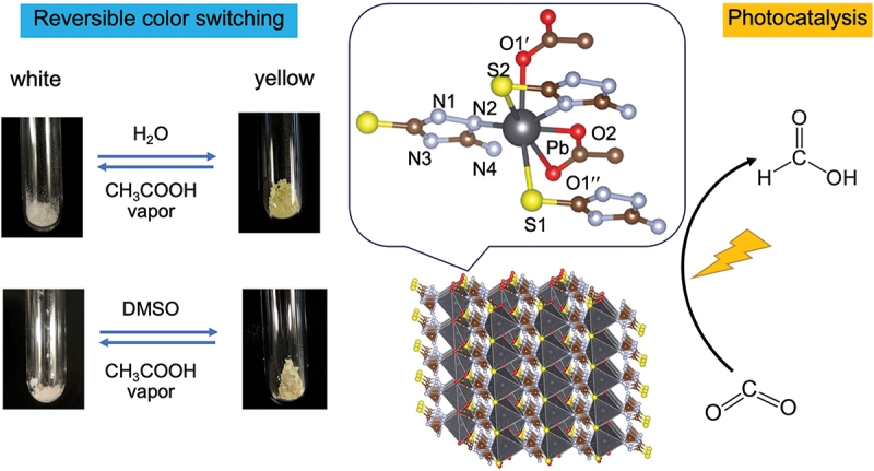
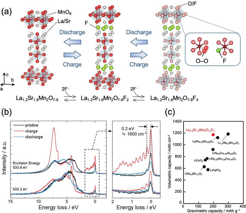
Discoveries and technological innovations over the past decade are transforming our understanding of the properties of ceramics, such as 'hard', 'brittle', and 'homogeneous'. For example, inorganic crystals containing molecular anions exhibit excellent secondary battery characteristics, and the fusion of inorganic solids and molecules results in innovative catalytic functions and physical properties. Different from the conventional ceramics such as metal oxides that are formed by monatomic cations and anions, unique properties and functions can be expected in molecular-incorporated inorganic solids, due to the asymmetric and dynamic properties brought about by the constituent molecular units. We name the molecular-incorporated inorganic materials that produce innovative properties and functions as supra-ceramics. In this article, we describe various kinds of supra-ceramics from the viewpoint of synthesis, analysis and physical properties/functions for a wide range of applications.

Keywords: CO2 conversion; Metal complexes; batteries; coordination polymers; metal-organic frameworks; organic-inorganic hybrids; perovskites; photocatalysts; proton conductors; solar cells.

Plain language summary

Recent discoveries/innovations are transforming ceramics by integrating molecular units, leading to new properties like enhanced battery performance and catalytic functions. Supra-ceramics, combining molecules and solids, promise innovative materials development.


Conflict of interest statement

No potential conflict of interest was reported by the author(s).

Figures

None
Graphical abstract
Figure 1.
Figure 1.
Our new concept of ‘supra-ceramics’, which provides a large space to develop materials with distinct physical properties and/or functions. The supra-ceramics are divided into two categories – endospheric and exospheric – depending on how molecular species are involved in inorganic solids.
Figure 2.
Figure 2.
New degrees of freedom originating from non-spherical molecular species (e.g. neutral molecules and charged ions) in inorganic solids and expected properties/functions, showing the ‘core of supra-ceramics’.
Figure 3.
Figure 3.
Typical and new synthesis routes for inorganic compounds that include molecular species (e.g. organic – inorganic hybrid perovskites and MOFs).
Figure 4.
Figure 4.
Non-ambient experiments involving X-ray diffraction profiles and FT-IR spectra have been conducted to elucidate the process for La2O2NCN synthesis using urea as a proanion.
Figure 5.
Figure 5.
Visualization of chemical structures of supra-ceramics based on various static and dynamic advanced measurements and computational approaches.
Figure 6.
Figure 6.
Development of RIXS local structure analysis equipment for molecular species consisting of light elements. (a) Ground-state potential energy surface obtained from RIXS vibrational spectra. (b) Vibrational energy range targeted by equipment to be developed in the near future. (c) A photograph of the RIXS instrument at NanoTerasu.
Figure 7.
Figure 7.
(a) Crystal structures of wurtzite-type ZnO, CuSCN, and inverse-oriented CuNCS. (b) Calculated pDOS for CuSCN and inverted CuNCS. The energy states’ valence-band top is set to 0 eV on the horizontal axis.
Figure 8.
Figure 8.
Photoluminescence spectra of Eu2+-doped BaCN2 phosphor. (a) Temperature dependence of emission spectrum under excitation at 460 nm. (b) Emission spectrum under static high pressures at room temperature.
Figure 9.
Figure 9.
Examples of water-responsive supra-ceramics: (a) luminescence-switchable (PyC3)2[ReN(CN)4] and (b) polarity-switchable K2MnN(CN)4. (c) P – E hysteresis loop of K2MnN(CN)4⋅H2O.
Figure 10.
Figure 10.
A new photofunctional Pb/S-based coordination polymer with the formula [Pb(ATAT)(OAc)]n (ATAT = 3-amino-5-mercapto-1,2,4-triazole, OAc = acetate). Reproduced from ref. [58]. Copyright 2024, American Chemical Society.
Figure 11.
Figure 11.
(a) Schematic of structures for [Pb(x-SPhOMe)2]n (x = ortho (KGF-32), meta (KGF-33), and para (KGF-34)). From left to right: coordination modes of SPhOMe ligands, local structures around Pb(II) ions, (–Pb – S–)n dimensionality, crystal structure, and photographs of corresponding samples. (b) UV–vis – nir spectra of KGF-32, −33 and − 34. (c) Schematic of band diagrams of KGF-32, −33, and − 34. (d) Results of TRMC measurements.
Figure 12.
Figure 12.
(a) Schematic of optical magneto-electric effects in (R/S-MPA)2CuCl4. (b) Temperature dependence of difference optical absorption coefficient. The magnetization is also plotted against temperature. The upper pictures are CCD images of the intensity difference.
Figure 13.
Figure 13.
(a) Illustration of the reconstructed reciprocal lattices for the two twin components (blue and orange spots) shown on top of the unwarped, non-symmetry-averaged precession image from the diffraction data (black spots). The image is aligned with the (hk0)p plane, with the blue twin aligned with the (210) vector and (001) plane as the upward and projection directions, and the orange twin aligned with the (1ˉ20) vector and (001ˉ) plane. (b) Real-space crystal structure depictions of the vacancy-ordered superstructure at the precise orientation dictated by the twin row to illustrate the un-defective α-FAPbI3 present at the interface. Unit cells for the twin components of the superstructure (blue, orange) and parent structure (dashed black) are drawn on top of both reciprocal and real space images. Reproduced from ref. [66]. Copyright 2023, American Chemical Society.
Figure 14.
Figure 14.
(a) Crystal structure and (B) PXRD patterns before/after mechanical milling of a CuFe PBA (K2x/3CuII[FeIIxFeIII1−x(CN)6]2/3Ł1/3·nH2O). (b) Cross-section SEM images of crystalline and glassy CuFe PBA. (c) A photograph of the CuFe PBA glass monolith prepared by uniaxial pressing. (d) Mössbauer spectrum of the CuFe PBA at room temperature.
Figure 15.
Figure 15.
(a) Discharge/charge scheme for La1.2Sr1.8Mn2O7–δF2 oxyfluoride. It has been unclear where O – O bonds and excess fluoride ions are located in the charged La1.2Sr1.8Mn2O7–δF2 oxyfluoride. (b) High-resolution RIXS spectra recorded at excitation energies of 530.2 and 530.8 eV for the pristine material and the material in the charged (3.0 V) and discharged (−1.5 V) states, respectively. The vibrational frequency of ~1600 cm−1 indicates the presence of O – O bonds. (c) Plots of the volumetric/gravimetric capacities for La1.2Sr1.8Mn2O7–δF2 oxyfluoride and cathode materials reported in lithium-ion batteries. Reproduced from ref. [79]. Copyright 2024, American Chemical Society.
Figure 16.
Figure 16.
(a) Synthesis scheme and crystal structure of KGF-9. (b) UV – visible diffuse-reflectance spectrum of KGF-9 and an action spectrum for CO2-to-formate conversion. The reactions were conducted under monochromatized light irradiation in a DMSO solution of BIH as a sacrificial electron donor. (c) Schematic of CO2 reduction over the KGF-9 surface. Reproduced from refs. [89,90]. Copyright 2022 and 2024, American Chemical Society.
Figure 17.
Figure 17.
(a) Schematic of doping of tris(bipyrazine)ruthenium(ii) complex into Zn-imidazole glass [Zn(HPO4)(H2PO4)2] to promote H+ transfer. (b) Photoexcited H+ conductivity of the composite at 303 K. Blue highlights demonstrate light irradiation with different intensities. (c) Cycling stability of the photoexcited H+ conductivity.
Figure 18.
Figure 18.
(a) Image of regular arrangements of organic molecules on an inorganic crystal surface. (b) Image of the anisotropic growth of MOF crystals on the surface.
Figure 19.
Figure 19.
(a) Schematic of the RuRe-adsorbed TiO2/PCN hybrid photocatalyst. (b) Effect of TiO2 modification (27 wt%) on CO2 reduction by RuRe (6.9 μmol g−1) adsorbed PCN (λ > 400 nm), where the reduction was performed in an acetonitrile/triethanolamine (TEOA) mixture. Here, TEOA acts as a sacrificial reductant that consumes holes generated in the valence band of PCN. (c) Time-dependent transient absorption signals of PCN and TiO2 (27 wt%)/PCN observed at 1800 cm−1. Reproduced from ref. [100]. Copyright 2017, American Chemical Society.
Figure 20.
Figure 20.
(a) Schematic of 1,4-arylation of cyclohexenone with phenylboronic acid on a ceria catalyst supporting a Rh nanocluster coordinated by NHC. (b) Initial and final state structures of the C – C bond formation step calculated for the catalytic reaction with and without NHC, and the corresponding energy diagrams. (c) Charge density difference calculated for H2TMAP adsorbed onto the LAS surface. Yellow and light-blue regions represent charge accumulation and depletion, respectively. VESTA was used to draw these structures. [103].
Figure 21.
Figure 21.
(a) Procedures used for the interlayer modification of K2LaTa2O6N. (b) H2 evolution over time using the K2LaTa2O6N-based materials under visible light (λ > 400 nm). Reaction conditions: catalyst, 50 mg (Pt photodeposited in situ); reactant solution, aqueous methanol (10 vol%, 140 mL); light source, 300 W xenon lamp with a cutoff filter. (c) Schematic of the reaction mechanism by which EA-intercalated K2−xHxLaTa2O6N reacts with H2PtCl6 to form Pt nanoparticles under illumination. Reproduced from ref. [108]. Copyright 2023, royal society of chemistry.
Figure 22.
Figure 22.
(a) Chemical and schematic molecular structures of TAMT3+ and TAT3+. Carbon numbering of triptycene is shown in the framework of TAMT3+. (b) Illustrations of the formation of a surface-passivation layer for a perovskite solar cell (PSC) using (TAMT)I3 and (TAT)I3. (c) Time-dependence of the normalized PCE of PSCs with/without a passivation layer of (TAMT)I3. The chemical composition of the perovskite layer of the PSC is MA0.13FA0.87PbI2.61Br0.39 (MA: methylammonium, FA: formamidinium). Reproduced from ref. [117].

References

    1. West AR. Solid state chemistry and its applications. UK: Wiley; 2014.
    1. Kageyama H, Hayashi K, Maeda K, et al. Expanding frontiers in materials chemistry and physics with multiple anions. Nat Commun. 2018;9(1):772. doi: 10.1038/s41467-018-02838-4 - DOI - PMC - PubMed
    1. Harada JK, Charles N, Poeppelmeier KR, et al. Heteroanionic materials by design: progress toward targeted properties. Adv Mater. 2019;31(19):e1805295. doi: 10.1002/adma.201805295 - DOI - PubMed
    1. Maeda K, Takeiri F, Kobayashi G, et al. Recent progress on mixed-anion materials for energy applications. Bull Chem Soc Jpn. 2022;95(1):26–28. doi: 10.1246/bcsj.20210351 - DOI
    1. Kojima A, Teshima K, Shirai Y, et al. Organometal halide perovskites as visible-light sensitizers for photovoltaic cells. J Am Chem Soc. 2009;131(17):6050–6051. doi: 10.1021/ja809598r - DOI - PubMed

LinkOut - more resources