. 2024 Nov 19;15(1):9867.
doi: 10.1038/s41467-024-53078-8.

Control of spatio-temporal patterning via cell growth in a multicellular synthetic gene circuit

Affiliations

Control of spatio-temporal patterning via cell growth in a multicellular synthetic gene circuit

Marco Santorelli et al. Nat Commun. .

Abstract

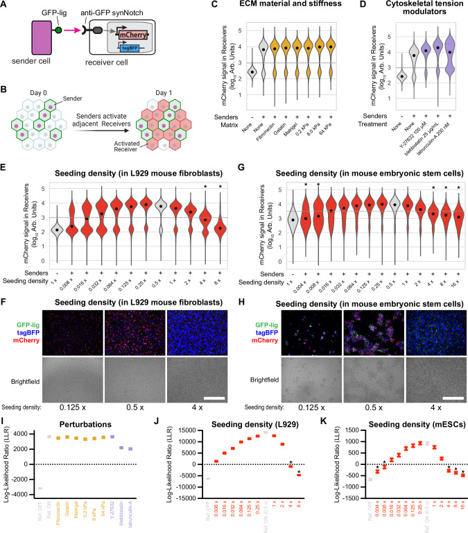
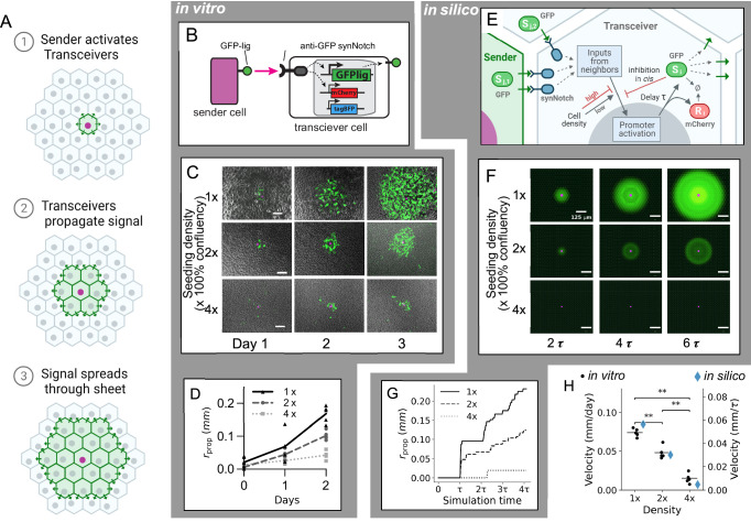
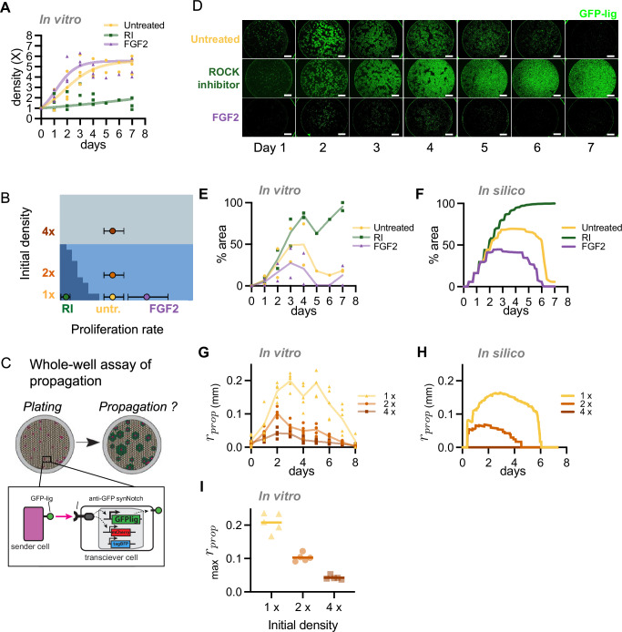
A major goal in synthetic development is to build gene regulatory circuits that control patterning. In natural development, an interplay between mechanical and chemical communication shapes the dynamics of multicellular gene regulatory circuits. For synthetic circuits, how non-genetic properties of the growth environment impact circuit behavior remains poorly explored. Here, we first describe an occurrence of mechano-chemical coupling in synthetic Notch (synNotch) patterning circuits: high cell density decreases synNotch-gated gene expression in different cellular systems in vitro. We then construct, both in vitro and in silico, a synNotch-based signal propagation circuit whose outcome can be regulated by cell density. Spatial and temporal patterning outcomes of this circuit can be predicted and controlled via modulation of cell proliferation, initial cell density, and/or spatial distribution of cell density. Our work demonstrates that synthetic patterning circuit outcome can be controlled via cellular growth, providing a means for programming multicellular circuit patterning outcomes.


Conflict of interest statement

Competing interests L.M. is an inventor on a synNotch patent for applications in cancer cell therapy licensed to Gilead. The remaining authors declare no competing interests.

Figures

Fig. 1
Fig. 1. Screening of mechanical perturbations reveals cell density-dependence of synNotch receptor activation.
A Schematic of Sender-Receiver synNotch signaling. Membrane-bound GFP-ligand in Senders binds synNotch in Receivers cleaving synNotch, freeing the intracellular domain (tTA-VP64) to translocate to the nucleus and activate mCherry reporter. B Schematic of synNotch signaling assay. Senders and Receivers are co-cultured at a 1:1 ratio and mCherry activation in receivers is measured at 24 h. CE Violin plots depict the distributions of mCherry fluorescence (log10 scale) measured via FACS in L929 Receiver cells (n = 4660–6733 cells) cultured in the indicated conditions for 24 h, seeded at an overall density of “1x” (1250 cells/mm2, counting Senders and Receivers), except where indicated otherwise. In (C), SynNotch signaling assay is performed with cells on different growth substrate materials and stiffnesses, in (D) with chemical modulators of cytoskeletal tension, in (E) with different initial cell densities at the same Senders:Receivers ratio 1:1. mCherry signal is specifically measured in Receiver cells (Fig. S1 shows gating scheme). Gray violin plots are reference samples for OFF and ON Receiver states. Black dots indicate medians. Dashed gray lines indicate the separation between ON and OFF populations. * indicates the sample is more likely OFF than ON, as determined by the log-likelihood ratio (LLR). Representative bright field and fluorescent micrographs of L929 (F) and mES (H) sender/receiver co-culture after 24 h of culture at the indicated densities. GFP-lig is expressed in senders, tagBFP in the receivers. Scale bars 500 µm. G Violin plots of mCherry fluorescence in mESCs Receivers after 24 h of coculture with mESCs Senders at the indicated densities, 1x is 6000 c/mm2. Dashed gray lines and * as in (E). IK Plots of the LLR calculated for each sample. The circle represents the LLR of the measured data and the error bars denote 95% CI with n = 1e6, calculated by bootstrapping. Points above zero indicate the sample resembles the ON state more than the OFF state. Error bars represent 95% confidence intervals (see “Methods”). All experiments were repeated at least 3 times with similar results. Source data are provided as Source Data file.
Fig. 2
Fig. 2. High cell density represses global mRNA production and reduces the expression level of membrane-associated synNotch signaling proteins which have short half-lives.
A Average of total RNA amount per L929 cell after 24 h of culture at the indicated densities as measured by spectrophotometer (Nanodrop). Lighter dots indicate individual experiment medians, darker dots the average of those. n = 3 experiments. B Fluorescence intensity levels read via FACS of different proteins at increasing cell density. L929 fibroblasts were analyzed by FACS 24 h after seeding at the indicated densities (1 x is 1250 cells/mm2). parental: unmodified L929; receivers: anti-GFP synNotch driving mCherry cells; sender: L929 cells expressing GFP-lig (PDGFR-GFP) on their surface; cytoplasmic GFP cells: L929 cells engineered to overexpress cytoplasmic GFP. SynNotch levels are measured via immunofluorescence with an antibody that recognizes a small peptide tag at the N-terminus of the synNotch protein (anti-myc-tag). 4000 or more cells per distribution are displayed, black dots indicate the medians of each distribution. Fluorescence levels were normalized as fold changes from the negative control, and plotted with a log10 scale. Lighter dots: individual experiment medians; darker and larger dots: average of those. n = 3 experiments. C Representative micrograph pictures of bright field and green fluorescence of L929 cells expressing GFP-lig, 24 h after being seeded at the indicated densities. 1x is 1250 cells/mm2. Scale bar 500 µm. See Supplementary Fig. S7 for results of similar experiments in mES cells. D, E Degradation kinetics of cytoplasmic GFP versus membrane-bound GFP-lig (see section “Measure of GFP and PDGFR-GFP half-life” in the “Methods”). L929 (D) and mES cells (E) are engineered to express cytoplasmic or membrane-bound GFP in a dox-controllable manner. The graphs report expression values for GFP over time measured via FACS after its expression is repressed via the small molecule Doxycycline at day 0. Normalized experimental means ± s.e.m. are reported. n = 3 experiments. Dark green: GFP levels; Light green: GFP-lig. Black horizontal dotted line: half maximum fluorescence. Colored vertical dotted lines were traced to infer proteins’ half-lives. Vertical error bars: s.e.m. Solid lines are normalized averages of 3 medians from 3 individual experiments. All experiments were repeated at least 3 times with similar results. Source data are provided as Source Data file.
Fig. 3
Fig. 3. Cell density tunes the velocity of signal propagation in a synNotch-based spatial propagation circuit.
A Schematic of signaling wave propagation (green) in a monolayer of transceiver cells (gray) initiated by a sender cell (purple nucleus). BD The in vitro Transceiver circuit propagation. B Membrane-bound GFP-ligand in Senders binds synNotch in Transceiver cells, cleaving synNotch, freeing the intracellular domain to translocate to the nucleus and activate its target genes: a GFP-ligand cassette, and an mCherry reporter cassette. Receiver cells also constitutively express a tagBFP marker. C Signal propagation over time. Micrograph images of propagation assays in vitro centered around a representative sender cell (purple) at the indicated time points and at the indicated initial density (1x is 1250 cells/mm2). Bright field (grayscale) is overlaid with GFP signal (green) and nuclear infrared fluorescent marker expressed in sender cells (purple). Scale bar 100 μm. See Supplementary Movies 1–3 for time-lapses. D Graph of propagation radius rprop over time for three cell densities (n = 5 foci). EG A computational model of Transceiver signaling. E Schematic of the model. A sender cell (left) presents GFP ligand s (green ellipsoid and triangles) to a Transceiver cell (center, “i”). Ligand from cell i’s neighbors (“j”) activates SynNotch receptors (blue). Activated SynNotch stimulates production of ligand and a reporter r (red ellipsoid) after a time delay τ. The production rate depends on cell density. The ligand s also inhibits its production (“cis-inhibition”). Ø indicates degradation. F In silico simulation of transceiver signaling, where green is GFP ligand, purple is a sender cell at the indicated times and cell densities of 1x, 2x, and 4x (without cell growth). Scale bar 125 μm. See Supplementary Movie 4 for time-lapse. G Propagation velocity (rprop) in silico for densities of 1x, 2x, and 4x. H Strip plot of propagation velocity in vitro (black dots; horizontal line indicates mean) and in silico (blue diamonds) at indicated cell densities. n = 5 foci. **p < 0.01 (p = 7.937e−03 for all pairwise comparisons), two-sided Mann–Whitney–Wilcoxon test. All experiments were repeated at least 3 times with similar results. Source data are provided as a Source Data file.
Fig. 4
Fig. 4. Cell population growth over time leads to self-limiting activation of the synNotch-based spatial propagation circuit.
A Propagation and attenuation of signal over a 7-day time-course. Fluorescence micrographs of an isolated propagation focus from a 1:100 sender:transceiver co-culture plated at a density of 1250 cells/mm2 (1x) at the indicated time point (days). GFP-lig (PDGFR-GFP) produced by senders and activated transceivers is shown in green, and mCherry (reporter for synNotch activation in transceivers, see schematic in Fig. 3B) is shown in red. Scale bar 100 μm. See Supplementary Movies 5 and 6 for time-lapse movies. B Cell density measured over time. Black dots indicate cell density of sender-transceiver co-cultures (n = 2–4 technical replicates, mean ± s.d.), measured by automated cell counting. The thick light blue line shows the best-fit logistic growth curve (thinner blue lines: 80% CI). C Quantification of the signaling area over time for in vitro and simulated Transceivers (black circles and blue curve, respectively). In vitro co-culture (1:100 ratio) was performed as in (A); n = 2–4 technical replicates, mean ± s.d. In silico simulation with growth was performed with one Sender on an 80 × 80 Transceiver lattice with an initial density of 1x, using the best-fit logistic growth curve from (B). D Renderings of GFP and mCherry levels in the Transceiver simulation at daily time-points. The mCherry reporter (second row, red), given a 10x slower degradation rate, persists for many days after attenuation, similarly to the in vitro time-course (A). See Supplementary Movie 7 for time-lapse. All experiments were repeated at least 3 times with similar results. Source data are provided as a Source Data file.
Fig. 5
Fig. 5. In silico screening of regimes of initial density and growth rate reveals a morphospace of signal propagation behaviors.
Theoretical dependence of qualitative (A) and quantitative (B) Transceiver activation on the parameters of cell proliferation. A A phase diagram showing distinct qualitative behaviors as a function of the intrinsic proliferation rate (g) and initial cell density (ρ0). The carrying capacity ρmax is held constant to its best-fit value in Fig. 4 (see “Methods” for more details, and Supplementary Fig. S15 for a 3D phase diagram including ρmax). Each simulation contains a 50 × 50 lattice of Transceivers with one Sender cell. After simulation, dynamics were classified into distinct phases of attenuated (gray), limited (light blue), or unlimited (dark blue) propagation (see “Methods” for details of classification). Black squares highlight exemplary parameter sets shown in (C). B The maximum area achieved by the propagation disc, superimposed on the phase diagram in (A) as white circles of diameter proportional to the area of signaling, see legend on the graph. C Example time-courses and simulation renderings for each phase of (A), corresponding to the black squares in (A). See Supplementary Movie 8 for time-lapse. D, E Illustrative graphs highlighting how the timing of Transceiver (de)activation depends on the parameters of growth. D The logistic growth equation, with parameters g, ρ0, ρmax. E Growth curves for the parameter sets in (C). Above ρchigh (indicated as ρcrit above the dotted line), signaling shuts down. Simulations in the limited phase cross the threshold during the time-course, while those in the other phases remain on either side of ρchigh.
Fig. 6
Fig. 6. Control of Transceiver activation area by manipulating cell proliferation rate and initial cell density.
A Time-course of cell density measures for cells grown in presence of growth-modulating drug as indicated: Untreated (yellow circles), FGF2 (violet triangles), or ROCK-inhibitor (RI; green squares). Automated cell counting was used to measure density (symbols: experimental means from n = 3 experiments) and parametrize the logistic growth equation (solid lines of corresponding color). “Untreated” sample reproduced from Fig. 3B. For similar experiments with other treatments see Fig. S16A. B Theoretical phase diagram of Transceiver propagation behavior as a function of proliferation rate (g) and initial cell density (ρ0) (see Fig. 4A), with markers indicating the fitted parameters of different experimental conditions. The circle represents the best-fit growth rate based on growth curve data and the error bars denote 90% CI with n = 1e6, calculated by bootstrapping. C Schematic of the whole-well propagation assay. A co-culture of senders (purple) and transceivers (brown) is plated in a culture well at time t = 0. Each sender acts as a propagation focus (inset diagram), and the distribution of ligand produced in the well (green) over time is assessed by fluorescence imaging. This assay allows quantification of propagation without isolation of single propagation foci. D Time-series micrographs of 1:100 sender:transceiver co-cultures plated at 1x density (1250 cells/mm2) under various drug treatments. Senders and activated transceivers produce GFP (green). Scale bar 1 mm. Note the plastic well border produces a circular green artifact. E Percent of the well in (D) covered by GFP fluorescence over time (experimental means from n = 2 experiments). For similar experiments with other treatments see Fig. S16B, C. F Simulated results for propagation area over time in the conditions of in vitro parameters of (D). G in vitro propagation of single foci over time for different initial densities. Y-axis is propagation radius (rprop) (symbols: radii of 5 individual foci). H Simulated results corresponding to in vitro conditions of (G). I Peak propagation radius in vitro for different initial densities (n = 5 foci, bars indicates mean). See also Fig. S16. Source data are provided as Source Data file.
Fig. 7
Fig. 7. Spatial patterns of cell density produce millimeter-scale activation patterns and kinematic waves.
A Left—phase diagram of qualitative behaviors of transceiver activation as a function of intrinsic proliferation rate (g) and initial cell density (r0) for t = 2.7 days. Top right—Schematic of spatial pattern of density in a culture well, S = signaling, NS = non signaling. Bottom right—signal propagation simulation with initial condition of patterned cell density. Green represents the GFP concentration at steady-state [GFP]SS. B, C In vitro density and signaling patterns. B Stitched epifluorescence micrographs of a culture well seeded with a sender:transceiver co-culture (1:100 ratio) in a spatial pattern of initial density (average of 2x) and imaged at 64 h of culture. Scale bar 2 mm. DAPI staining was used as a cell density readout (see Fig. S19B). Yellow box quantified in (C). C Fluorescence profiles showing the anti-correlated DAPI and GFP patterns, n = 1 profile shown. See Fig. S19 for the cell density pattern method. D, E In silico modeling predicts long-range kinematic waves over time. D Phase diagrams at three time-points with logarithmic y-axes. The density range between ρclow and ρchigh (white dotted and dashed lines) is optimal for signaling. E Modeling results of signal propagation in a non-uniform cell density field. Green is [GFP]SS. Between ρclow and ρchigh (white dotted and dashed lines) is optimal for signaling. F, G Synthetic kinematic wave generated by a density pattern in vitro. F Epifluorescence micrographs of a culture well seeded with 1:100 senders:transceivers in a spatial pattern of density (average of 1x, i.e., 1250 c/mm2) and imaged daily. Green indicates activated transceivers, blue is correlated to cell number. Scale bar 2 mm. The yellow box region is quantified in (G). See Supplementary Movies 9–12 for time-lapse movie of this dataset, and Figs. S19 and 20 for more examples and details. G Spatial profile of GFP fluorescence in (F) over time. White dots show the mean wavefront position, which has a velocity of 0.67 ± 0.18 mm/day (mean ± s.d.). All experiments were repeated at least 3 times with similar results. Source data are provided as a Source Data file.

References

    1. Thompson, D. W. On Growth and Form (Dover publication, New York, 1917).
    1. Kobitski, A. Y. et al. An ensemble-averaged, cell density-based digital model of zebrafish embryo development derived from light-sheet microscopy data with single-cell resolution. Sci. Rep.5, 8601 (2015). - PMC - PubMed
    1. Feroze, R., Shawky, J. H., von Dassow, M. & Davidson, L. A. Mechanics of blastopore closure during amphibian gastrulation. Dev. Biol.398, 57–67 (2015). - PMC - PubMed
    1. Zallen, J. A. & Goldstein, B. Cellular mechanisms of morphogenesis. Semin. Cell Dev. Biol.67, 101–102 (2017). - PMC - PubMed
    1. Fukaya, T. Dynamic regulation of anterior-posterior patterning genes in living Drosophila embryos. Curr. Biol.31, 2227–2236.e6 (2021). - PubMed

Publication types

Substances

LinkOut - more resources