. 2025 Jan:112:107168.
doi: 10.1016/j.ultsonch.2024.107168. Epub 2024 Nov 19.

Experimental and numerical research on jet dynamics of cavitation bubble near dual particles

Affiliations

Experimental and numerical research on jet dynamics of cavitation bubble near dual particles

Yuning Zhang et al. Ultrason Sonochem. 2025 Jan.

Abstract

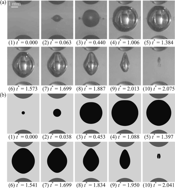
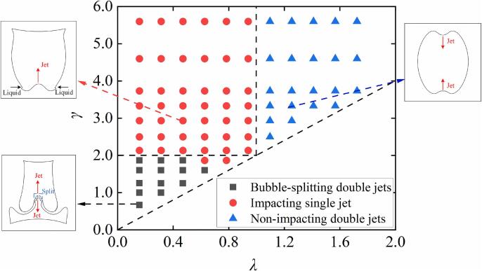
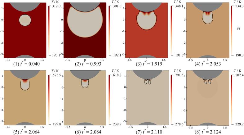
The current paper delves into the jet dynamics arising from a cavitation bubble in proximity to a dual-particle system, employing both experimental methodology and numerical simulation. The morphological development of a laser-induced bubble as well as the production of jets are captured by utilizing high-speed photography. The principles of bubble morphology evolution and jet formation are revealed by a OpenFOAM solver, which takes into account the effects of two-phase fluid compressibility, phase changes, heat transfer, and surface tension. Fluid temperature variations induced by bubble oscillations are discussed. The results indicate that the jet dynamics can be categorized into three cases, i.e. bubble-splitting double jets, impacting single jet, non-impacting double jets. For bubble-splitting double jets, bubble splitting is induced by an annular pressure gradient towards the bubble axis. This resulted in the production of two unequal-sized sub-bubbles, which subsequently produced double jets in opposite directions. The fluid temperature close to the bubble interface is low, while the bubble center is high. For impacting single jet, it is induced by a conical pressure gradient towards the nearest particle and the jet impacts the particle. The fluid temperature is low near the jet and high near the particle. When the jet penetrates the bubble interface, the temperature inside the bubble reaches its peak. For non-impacting double jets, they are induced by pressure gradients facing each other and they do not impact particles. The temperature inside the bubble increases with the proximity of the two jets.

Keywords: Cavitation bubble; High-speed photography; Jet dynamics; Numerical simulation; Pressure gradient.


Conflict of interest statement

Declaration of competing interest The authors declare that they have no known competing financial interests or personal relationships that could have appeared to influence the work reported in this paper.

Figures

Fig. 1
Fig. 1
Diagram of the experimental equipment arrangement.
Fig. 2
Fig. 2
Steps for simulating bubble oscillations.
Fig. 3
Fig. 3
Impact of MaxCo on the bubble equivalent radius (Req). Rmax = 1.60 mm, λ = 1.10, and γ = 2.41.
Fig. 4
Fig. 4
Mesh independence results. Rmax = 1.60 mm, λ = 1.10, and γ = 2.41.
Fig. 5
Fig. 5
Comparisons of bubble morphology evolution. (a) Experimental results. (b) Numerical results. In the simulation results, black areas correspond to bubbles, gray areas to liquids, and dark gray areas to particles. Rmax = 1.60 mm, λ = 1.10, and γ = 2.41.
Fig. 6
Fig. 6
Comparison of experimentally measured displacements and simulated predicted displacements at two feature points. The blue circles/lines indicate the displacement of the rightmost point of the bubble interface. The red circles/lines indicate the displacement of the lowermost point of the bubble interface. Rmax = 1.60 mm, λ = 1.10, and γ = 2.41. (For interpretation of the references to colour in this figure legend, the reader is referred to the web version of this article.)
Fig. 7
Fig. 7
Main features and classifications of the jet dynamics near the dual-particle system. Three black dashed lines serve as the dividing line between the three cases. Rmax = 1.50 mm.
Fig. 8
Fig. 8
Bubble morphology evolution and jet formation for the case of bubble-splitting double jets. (a) Experimental results. (b) Simulated results. (c) Evolution of the jet. In the simulated results, the left part of each subplot indicates the velocity field, and arrows indicate the velocity vectors. The right part indicates the pressure field. The gray parts indicate the particles. λ = 0.16, γ = 0.67, and Rmax = 1.50 mm.
Fig. 9
Fig. 9
The temperature field evolution surrounding the bubble for the case of bubble-splitting double jets. The solid black lines are the bubble interface. The gray parts indicate the particles. λ = 0.16, γ = 0.67, and Rmax = 1.50 mm.
Fig. 10
Fig. 10
Cavitation bubble morphology evolution and jet formation for the case of impacting single jet. (a) Experimental results. (b) Simulated results. (c) Evolution of the jet. In the simulated results, the left part of each subplot indicates the velocity field, and arrows indicate the velocity vectors. The right part indicates the pressure field. The gray parts indicate the particles. λ = 0.47, γ = 2.5, and Rmax = 1.50 mm.
Fig. 11
Fig. 11
Mechanisms of jet formation for the case of impacting single jet. The left part of each subplot indicates the velocity field, and arrows indicate the velocity vectors. The right part indicates the pressure field. The gray parts indicate the particles. λ = 0.16, γ = 3.33, and Rmax = 1.50 mm.
Fig. 12
Fig. 12
The temperature field evolution surrounding the bubble for the case of impacting single jet. The solid black line is the bubble interface. The gray parts indicate the particles. λ = 0.47, γ = 2.5, and Rmax = 1.50 mm.
Fig. 13
Fig. 13
Cavitation bubble morphology evolution and jet formation for the case of non-impacting double jets. (a) Experimental results. (b) Simulated results. (c) Evolution of the jet. In the simulated results, the left part of each subplot indicates the velocity field, and arrows indicate the velocity vectors. The right part indicates the pressure field. The gray parts indicate the particles. λ = 1.34, γ = 3.00, and Rmax = 1.50 mm.
Fig. 14
Fig. 14
The temperature field evolution surrounding the bubble for the case of non-impacting double jets. The solid black line is the bubble interface. The gray parts indicate the particles. λ = 1.34, γ = 3.00, and Rmax = 1.50 mm.
Fig. 15
Fig. 15
Effect of particle spacing parameter γ on the jet behaviour for λ = 0.16. The arrows represent the velocity vectors. (a) γ = 0.67. (b) γ = 1.60. (c) γ = 2.13. (d) γ = 5.6. Rmax = 1.50 mm.
Fig. 16
Fig. 16
Effect of particle spacing parameter γ on the jet behaviour for λ = 0.63. The arrows represent the velocity vectors. (a) γ = 1.60. (b) γ = 2.13. (c) γ = 5.60. Rmax = 1.50 mm.
Fig. 17
Fig. 17
Effect of particle spacing parameter γ on the jet behaviour for λ = 1.25. The arrows represent the velocity vectors. (a) γ = 3.33. (b) γ = 5.60. Rmax = 1.50 mm.
Fig. 18
Fig. 18
Velocity variations of characteristic points on bubble interface for the case of bubble-splitting double jets. (a) Lowermost point of the bubble interface on Y-axis. (b) Uppermost point of the bubble interface on Y-axis. λ = 0.16 and Rmax = 1.50 mm.
Fig. 19
Fig. 19
Velocity variations of characteristic points on bubble interface for the case of impacting single jet. (a) Lowermost point of the bubble interface on Y-axis. (b) Uppermost point of the bubble interface on Y-axis. Rmax = 1.50 mm.
Fig. 20
Fig. 20
Variations in jet velocity versus time for the case of non-impacting double jets. (a) Upward jet. (b) Downward jet. λ = 1.25 and Rmax = 1.50 mm.

References

    1. Sun J., Ge X., Zhou Y., Liu D., Liu J., Li G., Zheng Y. Research on synergistic erosion by cavitation and sediment: a review. Ultrason. Sonochem. 2023;95 - PMC - PubMed
    1. Wang C., Zhang Y.X., Hou H.C., Zhang J.Y., Xu C. Entropy production diagnostic analysis of energy consumption for cavitation flow in a two-stage LNG cryogenic submerged pump. Int. J. Heat Mass Transf. 2019;129:342–356.
    1. Wang X., Liang Q., Yang Y., Shen J., Feng Z., Zhang Y., Zhang Y. Dynamics of single cavitation bubble collapse jet under particle-wall synergy. Phys. Fluids. 2024;36(10)
    1. Kan K., Binama M., Chen H.X., Zheng Y., Zhou D.Q., Su W.T., Muhirwa A. Pump as turbine cavitation performance for both conventional and reverse operating modes: a review. Renew. Sustain. Energy Rev. 2022;168
    1. Yu J., Wang X., Hu J., Shen J., Zhang X., Zheng X., Zhang Y., Yao Z. Laser-induced cavitation bubble near boundaries. J. Hydrodyn. 2023;35:858–875.

LinkOut - more resources