

Fracture Line Morphology and a Novel Classification of Pilon Fractures
- PMID: 39579007
- PMCID: PMC11787965
- DOI: 10.1111/os.14304
Fracture Line Morphology and a Novel Classification of Pilon Fractures
Abstract
Objective: Currently, there is no research that includes a comprehensive three-dimensional fracture mapping encompassing all types of Pilon fractures. Moreover, the existing classification systems for Pilon fractures exhibit only moderate to fair consistency and reproducibility. Additionally, some of these classification systems fail to accurately depict the morphological characteristics of the fractures. This study aimed to create a fracture map encompassing all types of Pilon fractures by three-dimensional fracture mapping. In addition, this study conducted a finite element analysis of the normal ankle joint, and based on the distribution of fracture lines and the stress distribution at the distal tibia, proposed a new classification for Pilon fractures.
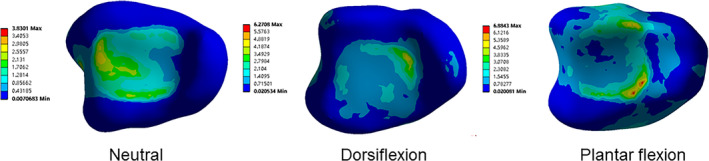
Methods: A retrospective analysis of Pilon fractures in our hospital from January 2018 to January 2024 was performed. A total of two hundred forty-four Pilon fractures were included, and their fracture lines were transcribed onto the tibia and fibula templates, and fracture maps and heat maps were created. A nonhomogeneous model of the ankle joint was constructed and verified, and the stress distribution on the distal tibia articular surface was measured and analyzed in three models (neutral, dorsiflexed, and plantarflexed model). Based on the fracture map and stress distribution, a five-column classification system for Pilon fractures was proposed, and the intraobserver and interobserver reliability was calculated using Cohen and Fleiss k statistics.
Result: The fracture line on the distal tibia articular surface showed a V-shaped distribution. One branch extended from the junction of the medial malleolar articular surface and the inferior tibial articular surface toward the medial malleolus. The other branch extended from the middle of the fibular notch to the posterior part of the medial ankle, toward the tibial shaft. The fibula fracture line mainly extended from the anterior and lower part of the lateral malleolus to the posterior and upper part. As evidenced by the neutral, dorsiflexed, and plantar flexion models, the stress on the posterolateral articular surface (posterolateral column) was low, while the majority of the stress was concentrated in the center. Three-column fractures were the most common, followed by two-column fractures. Using the five-column classification, the K-weighted values of interobserver and intraobserver analysis were 0.653 (p < 0.001) and 0.708 (p < 0.001), respectively.
Conclusions: In this study, the fracture line and morphological characteristics of Pilon fractures were analyzed in detail by three-dimensional mapping. In addition, this study conducted a finite element analysis of the stress distribution on the distal tibial joint surface of the normal ankle joint. Moreover, a novel classification system was proposed to reflect these findings. The new classification not only exhibits greater consistency, facilitating accurate communication of fracture characteristics among surgeons, but also aids in understanding the mechanisms of injury and formulating surgical strategies.
Keywords: classification; computed tomography; finite element analysis; fracture mapping; pilon fractures.
© 2024 The Author(s). Orthopaedic Surgery published by Tianjin Hospital and John Wiley & Sons Australia, Ltd.
Conflict of interest statement
The authors declare no conflicts of interest.
Figures


References
-
- Flett L., Adamson J., Barron E., et al., “A Multicentre, Randomized, Parallel Group, Superiority Study to Compare the Clinical Effectiveness and Cost‐Effectiveness of External Frame Versus Internal Locking Plate for Complete Articular Pilon Fracture Fixation in Adults,” Bone & Joint Open 2, no. 3 (2021): 150–163. - PMC - PubMed
-
- Bedi A., Le T. T., and Karunakar M. A., “Surgical Treatment of Nonarticular Distal Tibia Fractures,” Journal of the American Academy of Orthopaedic Surgeons 14, no. 7 (2006): 406–416. - PubMed
-
- Topliss C. J., Jackson M., and Atkins R. M., “Anatomy of Pilon Fractures of the Distal Tibia,” Journal of Bone and Joint Surgery. British Volume 87, no. 5 (2005): 692–697. - PubMed
-
- Mauffrey C., Vasario G., Battiston B., Lewis C., Beazley J., and Seligson D., “Tibial Pilon Fractures: A Review of Incidence, Diagnosis, Treatment, and Complications,” Acta Orthopaedica Belgica 77, no. 4 (2011): 432–440. - PubMed
-
- Tang X., Tang P. F., Wang M. Y., et al., “Pilon Fractures: A New Classification and Therapeutic Strategies,” Chinese Medical Journal, Peking 125, no. 14 (2012): 2487–2492. - PubMed
MeSH terms
LinkOut - more resources
Full Text Sources
Medical
Research Materials
