. 2024 Nov 23;14(1):29054.
doi: 10.1038/s41598-024-79945-4.

Microresonator photonic wire bond integration for Kerr-microcomb generation

Affiliations

Microresonator photonic wire bond integration for Kerr-microcomb generation

Alain Yuji Takabayashi et al. Sci Rep. .

Abstract

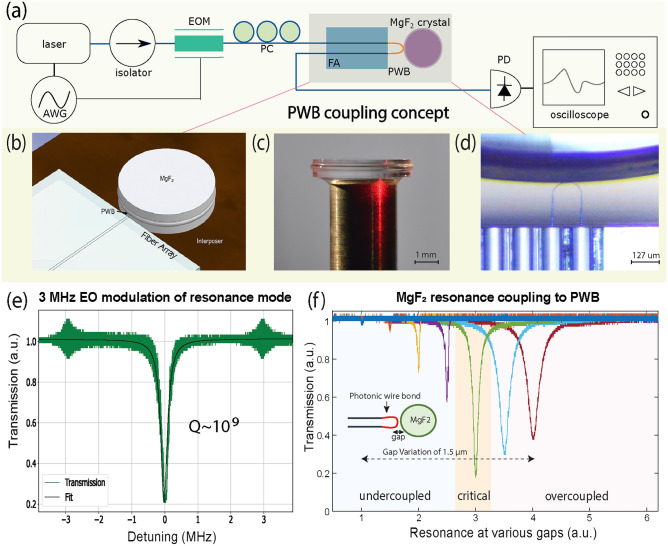
Extremely high-Q microresonators provide an attractive platform for a plethora of photonic applications including optical frequency combs, high-precision metrology, telecommunication, microwave generation, narrow linewidth lasers, and stable frequency references. Moreover, the desire for compactness and a low power threshold for nonlinear phenomena have spurred investigation into integrated and scalable solutions. Historically, crystalline microresonators with Q ∼ 109 were one of the first material platforms providing unprecedented optical performance in a small form factor. A key challenge, though, with these devices is in finding alternatives to fragile, bulky, and free-space couplers, such as tapered fibers, prisms, and cleaved fibers. Here, we present for the first time, the evanescent coupling of a photonic wire bond (PWB) to a MgF2-based microresonator to generate solitons and a pure, low-noise microwave signal based on Kerr-microcombs. These results open a path towards scalable integration of crystalline microresonators with integrated photonics. Moreover, because PWBs possess advantages over traditional coupling elements in terms of ease of fabrication, size, and flexibility, they constitute a more advanced optical interface for linear and nonlinear photonics.


Conflict of interest statement

Declarations. Competing interests: None of the authors have competing interests but we disclose in the interest of transparency that M.K. and J.J are co-founders of Enlightra. Additionally, T.N., Z.B., M.V.C, C.T., J.J, and L.J. have filed patent applications related, but not limited, to the subject matter disclosed in the manuscript.

Figures

Figure 1
Figure 1
Design and characterization of PWBs. (a) SEM micrograph of the PWBs written to the fiber cores of an eight-channel V-groove fiber array. (b) Microscope image showing four PWBs, each with a different extension length: 100 µm, 120  µm, 150 µm and 190 µm respectively. (c) Sub-micron-resolution thermo-reflectance image of a PWB indicating optical power concentration within the loopback. The insert table shows the optical power of PWB failure. (d) Fiber-to-fiber losses through the PWBs in (b) indicating losses formula image 1.7 dB at 1550 nm for the shortest PWB (blue curve 100 µm length). (e) Finite-element method simulation on the effective index of two TE modes (TEformula image is the blue curve, TEformula image is the pink curve) within the PWB as a function of cross-sectional geometry (PWB radius) to reach index-matching with MgF2 (green dashed line) at 1550 nm.
Figure 2
Figure 2
PWB-microresonator characterization in linear regime. (a) Experimental setup for testing the PWB-microresonator configuration in the linear regime, i.e., coupling ideality and Q-factor measurement. AWG arbitrary waveform generator, EOM electro-optical modulator, PC polarization controller, FA fiber, V groove array, PWB photonic wire bond, PD photodetector. (b) 3D rendering of the FA-PWB-crystal arrangement. (c) Photograph of a 4.92 mm MgF2 crystal with microresonator protrusion. (d) Microscope image of PWB on the FA facet coupled to the crystalline microresonator. (e) Linewidth measurement of a resonance with 3 MHz calibration sidebands, wherein a Lorentzian fit (black line) has been applied to the measured transmitted light (green line) and gives a linewidth of 240 kHz, corresponding to a Q-factor of formula image 109 at 1550 nm. (f) Evolution of resonance linewidth as a function of PWB-microresonator gap for a single resonance. All traces correspond to the same resonance and have been offset to better visualize the transition from undercoupled (left), to critically coupled (center), to overcoupled (right) states. Furthermore, the total displacement between undercoupled to overcoupled regimes is 1.5 formula imagem, starting from 0 formula imagem on the left.
Figure 3
Figure 3
PWB-microresonator characterization in nonlinear regime. (a) Experimental setup used in the nonlinear characterization of the PWB-microresonator system. EOM electro-optical modulator, PC polarization controller, EDFA erbium-doped fiber amplifier, BPF tunable bandpass filter, FA fiber, V groove array, PWB photonic wire bond, FBG tunable fiber Bragg grating notch filter, PD photodetector, OSA optical spectrum analyzer, ESA electrical spectrum analyzer, Servo PID servo controller. (b) A single soliton optical spectrum generated in a MgF2 microresonator with a fitted formula image envelope shown by the dashed red line. (c) ESA trace at a 10 Hz resolution bandwidth (RBW) for an 80 kHz span of the 14.25 GHz beatnote signal, which corresponds to the comb line spacing in the soliton state.
Figure 4
Figure 4
Quiet point hunting with PWBs. (a) Soliton spectra for a range of laser-resonance detunings from 3 to 5 MHz, where the modal crossings become visible after 4 MHz. (b) Visualization of the shift in microresonator repetition rate as a function of detuning. Point 1 indicates a normal operating point where the FSR varies linearly with detuning and Point 2 suggests a quiet point where the FSR versus detuning relation is effectively invariant. (c) Plot of the phase noise for the two points in (b) indicating around 10 dB noise suppression for point 2.

References

    1. Herr, T. et al. Temporal solitons in optical microresonators. Nat. Photon.8, 145 (2014).
    1. Kippenberg, T. J., Gaeta, A. L., Lipson, M. & Gorodetsky, M. L. Dissipative kerr solitons in optical microresonators. Science361, 1 (2018). - PubMed
    1. Svela, A. O. et al. Coherent suppression of backscattering in optical microresonators. Light Sci. Appl.9, 204 (2020). - PMC - PubMed
    1. Zhang, F. et al. Robust packaged fiber-microcavity device with over one billion Q-factor. http://arxiv.org/abs/2304.03179 (2023).
    1. Matsko, A. & Ilchenko, V. Optical resonators with whispering-gallery modes-part i: Basics. IEEE J. Sel. Top. Quantum Electron.12, 3–14 (2006).

LinkOut - more resources