. 2024 Nov 17;57(Pt 6):1871-1883.
doi: 10.1107/S1600576724010082. eCollection 2024 Dec 1.

Modulating phase segregation during spin-casting of fullerene-based polymer solar-cell thin films upon minor addition of a high-boiling co-solvent

Affiliations

Modulating phase segregation during spin-casting of fullerene-based polymer solar-cell thin films upon minor addition of a high-boiling co-solvent

Kuan-Hsun Lu et al. J Appl Crystallogr. .

Abstract

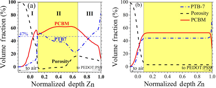
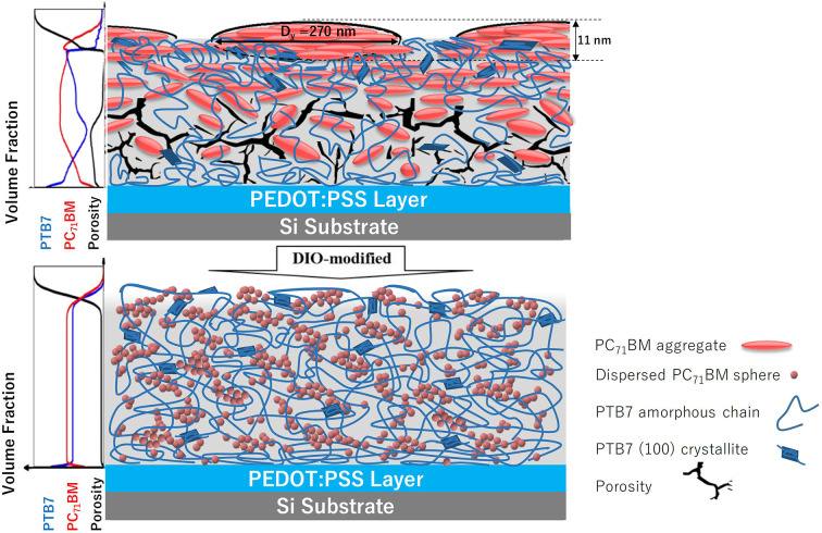
The impact of additives on the nanoscale structures of spin-cast polymer composite films, particularly in polymer solar cells, is a topic of significant interest. This study focuses on the blend film comprising poly(thieno[3,4-b]thio-phene-alt-benzodi-thio-phene) (PTB7) and [6,6]-phenyl-C71-butyric acid methyl ester (PC71BM), exploring how additives like 1,8-di-iodo-octane (DIO) influence the film structures spin-cast from chloro-benzene solution. Combined results of specular X-ray and neutron reflectivity, grazing-incidence small- and wide-angle X-ray scattering (GISAXS and GIWAXS), and X-ray photoelectron spectroscopy indicate that DIO could significantly enhance the dispersion of PC71BM and reduce composition inhomogeneity in the film. Time-resolved GISAXS-GIWAXS with 100 ms resolution further captures a rapid spinodal decomposition of the mixture within 1 s in the constant-evaporation stage of spin-casting. Further combined with parallel analysis of time-resolved UV-Vis reflectance, these findings reveal that DIO mitigates the spinodal decomposition process by accelerating solvent evaporation, which, in turn, decelerates phase segregation, leading to a nucleation-driven process. These observations provide mechanistic insights into the role of additives in controlling the nanostructural evolution of spin-cast films by altering the kinetics of solvent evaporation and phase separation during the spin-coating process.

Keywords: GISAXS; GIWAXS; X-ray reflectivity; additive effects; grazing-incidence small/wide-angle X-ray scattering; neutron reflectivity; polymer solar cells; spinodal decomposition.


Figures

Figure 1
Figure 1
(a) XR and NR data fitted (curves) using (b) the five-layer SLD models (solid and dashed profiles) for the same N-1.5 film, including the surface sublayer and two main sublayers of the active layer sitting on a PEDOT:PSS conducting layer on the silicon substrate. Note that an additional thin SiOx sublayer of ca 2 nm thickness above the Si substrate is used in the NR data fitting (which might be produced by UV–ozone treatment on the Si substrate and is sensitive to NR due to its relatively high ρN value compared with the pure Si substrate); the ρx value of this SiOx sublayer is, however, very close to that of the Si substrate, and therefore the SiOx sublayer is neglected in the XR data fitting. (c) Corresponding data of the D-1.5 film are fitted using (d) the four-layer SLD models. The vertical dashed lines in (b) and (d) mark the interfaces between the PTB7–PC71BM blend layer and the PEDOT:PSS conducting layer.
Figure 2
Figure 2
(a) Depth-dependent volume fraction (composition) profiles of PTB7 (blue dash–dotted curve) and PC71BM (red solid curve), together with porosity (black dashed curve), for the N-1.5 film along the film depth direction Zn (140 nm film thickness). The (I) surface zone, (II) main active layer and (III) interface zone above the PEDOT-PSS conducting layer are marked. The sadh–dotted line for 47% marks a reference volume fraction of PTB7 in the spin-cast solution. (b) Parallel information extracted for the D-1.5 film of a film thickness of 95 nm, showing a much smoother transition zone from the active layer to the PEDOT:PSS conducting layer.
Figure 3
Figure 3
(a) Surface topography, (b) phase contrast images (3 × 3 µm) and (c) 1D morphological cut along the red line marked in (a) for the N-1.5 film. (d)–(f) are the corresponding information for the D-1.5 film.
Figure 4
Figure 4
(a) The through-thickness C/S (or C1s/S2p) and dcSi/dN profiles deduced from XPS (in terms of sputter cycle N) for N-1.5, and (b) the corresponding data for the D-1.5 films. The dcSi/dN peak position corresponds to the interface between the PEDOT:PSS layer and the Si substrate. The big arrow in (a) marks the porosity effect on the non-trivial dcSi/dN values observed before reaching the PEDOT:PSS layer in the N-1.5 film.
Figure 5
Figure 5
(a) Observed and (b) simulated 2D GISAXS patterns of the N-1.5 film. Inset in (a) is a zoomed-in view of the scattering stripes centered at qy ≃ 0.018 nm−1. Selected comparisons of the measured (symbols) and simulated (solid curves) GISAXS line profiles along (c) in-plane and (d) out-of-plane directions of the corresponding 2D GISAXS patterns, at the respective qz or qy positions indicated. (e) Observed and (f) simulated 2D GISAXS patterns for the D-1.5 film; measured and fitted GISAXS line profiles in the (g) in-plane and (h) out-of-plane directions.
Figure 6
Figure 6
Cartoons illustrate the nanostructural features of PC71BM nanodomains for the N-1.5 (top) and D-1.5 (bottom) films, including the through-thickness composition profiles illustrated on the left-hand side. Note that the PC71BM aggregates (in red) are enriched and enlarged at and near the surface of the N-1.5 film. In contrast, relatively small PC71BM aggregates are distributed homogeneously in the D-1.5 film, with porosity largely eliminated.
Figure 7
Figure 7
Cartoon of the pair binding energy (as indicated; in units of kcal mol−1) of the four components in a CB solution containing DIO, PC71BM and PTB7 for spin-coating.
Figure 8
Figure 8
(a) Representative time-dependent GISAXS patterns taken with 100 ms resolution during spin-coating of the PTB7–PC71BM film from the sample solutions of CB without additive, over the spin-coating time indicated. The vertical arrows in (a) indicate the emergence and development of the vertical scattering stripes at qy ≃ 0.002 Å−1 over t = 2.4–2.8 s of the spin-coating time. (b) Parallel GISAXS patterns for the case with 3% DIO, showing no scattering stripes (see the movies in the supporting information for the complete spin-coating process).
Figure 9
Figure 9
(a) Time-resolved, in-plane GISAXS profiles selectively extracted at qz = 0.05 Å−1 from the corresponding 2D GISAXS patterns in Fig. 8 ▸(a), measured during spin-coating of the CB solution of PTB7/PC71BT, without DIO. The thick and curved arrows indicate the growth and decay of the intensity in the very low q region (<0.001 Å−1) during the early (t1), intermediate (t1t2) and late (t > t3) spin-coating stages. The thin long arrow indicates the growth and saturation of the SD peak at qy ≃ 0.002 Å−1. (b) Selected in-plane GISAXS profiles extracted at qz = 0.025 Å−1 (see Fig. S6 for details) for the film processed with 1.5% DIO. Data at t = 4, 48, 78 and 98 s are selectively fitted (solid curves) using a sphere model of radii of 53 ± 8, 56 ± 4, 60 ± 4 and 58 ± 3 nm, respectively. (c) The growth behaviors of Qinv (extracted from the corresponding time-resolved in-plane GISAXS profiles) during spin-coating of the PTB7–PC71BM films from the CB solutions, with the DIO concentrations indicated. (d) Time-dependent film thickness h (top) and film thinning rate dh/dt (bottom) measured using UV–Vis reflectance during film spin-coating without and with 3% DIO. The horizontal dotted lines label the constant-evaporation regions. The shaded zone marks the timing of SD in (a).
Figure 10
Figure 10
Schematic illustration of the effects of the DIO additive on modulating phase segregation in the PTB7–PC71BM blend during spin-coating from a CB/DIO (97:3 v/v) solution. The high boiling point of DIO accelerates the evaporation of the low-boiling-point CB during the spin-coating process. In the near-surface region (depicted by the graduated blue zone), the rapid evaporation of CB with high flux prevents excessive solute concentration at the surface, thereby inhibiting rapid phase segregation via spinodal decomposition. As CB quickly evaporates, the remaining PC71BM–PTB7 mixture becomes kinetically trapped in the DIO-rich environment, where the slow segregation of PC71BM leads to the formation of small PC71BM aggregates (represented by red spheres) a few nanometres in size. These small aggregates further interconnect into fractal-like clusters within the PTB7/DIO matrix, which consists of both amorphous chains and crystalline regions (depicted as wires and blocks). DIO, accounting for approximately 24% of the film’s volume fraction (as estimated from the solution composition after the exhausted evaporation of CB), is represented by the irregular orange patches. In contrast, Fig. 6 ▸ illustrates a film from which DIO was removed by vacuum evacuation.

References

    1. Babonneau, D. (2010). J. Appl. Cryst.43, 929–936.
    1. Cahn, J. W. & Hilliard, J. E. (1958). J. Chem. Phys.28, 258–267.
    1. Cahn, J. W. & Hilliard, J. E. (1959). J. Chem. Phys.31, 688–699.
    1. Chambon, F. & Winter, H. H. (1987). J. Rheol.31, 683–697.
    1. Chen, W., Nikiforov, M. P. & Darling, S. B. (2012). Energy Environ. Sci.5, 8045–8074.

LinkOut - more resources