Review
. 2025 Jan;12(4):e2411278.
doi: 10.1002/advs.202411278. Epub 2024 Dec 4.

Microfluidic Nanoparticle Separation for Precision Medicine

Affiliations
Review

Microfluidic Nanoparticle Separation for Precision Medicine

Zhenwei Lan et al. Adv Sci (Weinh). 2025 Jan.

Abstract

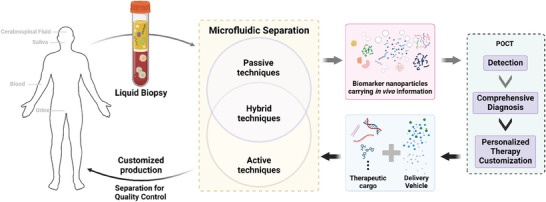
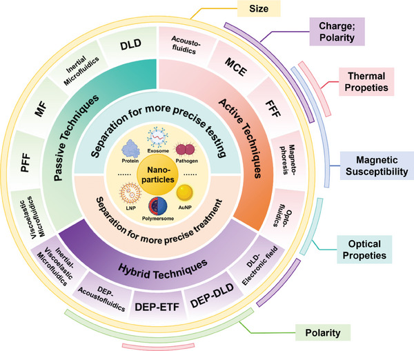
A deeper understanding of disease heterogeneity highlights the urgent need for precision medicine. Microfluidics, with its unique advantages, such as high adjustability, diverse material selection, low cost, high processing efficiency, and minimal sample requirements, presents an ideal platform for precision medicine applications. As nanoparticles, both of biological origin and for therapeutic purposes, become increasingly important in precision medicine, microfluidic nanoparticle separation proves particularly advantageous for handling valuable samples in personalized medicine. This technology not only enhances detection, diagnosis, monitoring, and treatment accuracy, but also reduces invasiveness in medical procedures. This review summarizes the fundamentals of microfluidic nanoparticle separation techniques for precision medicine, starting with an examination of nanoparticle properties essential for separation and the core principles that guide various microfluidic methods. It then explores passive, active, and hybrid separation techniques, detailing their principles, structures, and applications. Furthermore, the review highlights their contributions to advancements in liquid biopsy and nanomedicine. Finally, it addresses existing challenges and envisions future development spurred by emerging technologies such as advanced materials science, 3D printing, and artificial intelligence. These interdisciplinary collaborations are anticipated to propel the platformization of microfluidic separation techniques, significantly expanding their potential in precision medicine.

Keywords: microfluidic; nanomedicine; nanoparticles; precision medicine; separation.


Conflict of interest statement

The authors declare no conflict of interest.

Figures

Figure 1
Figure 1
The role of microfluidic nanoparticle separation in precision medicine. Microfluidic technologies, including active, passive, and hybrid techniques, enable the effective isolation of key biomarkers from patient‐derived biological fluids. In parallel, point‐of‐care testing (POCT) supports rapid detection and diagnosis, guiding the design of tailored treatment strategies. In producing personalized therapy, microfluidic techniques are essential for controlling nanoparticle synthesis and purification, thereby tuning their properties such as purity, particle size, and drug loading.
Figure 2
Figure 2
Microfluidic separation techniques for nanoparticles. Passive techniques include viscoelastic microfluidic, pinched flow fractionation (PFF), microfluidic filtration (MF), inertial microfluidic, and deterministic lateral displacement (DLD). Active techniques include acoustic fluidics, microfluidic chip electrophoresis (MCE), field flow fractionation (FFF), magnetophoresis, and optofluidics. Hybrid techniques mainly include the combination of inertial microfluidic and viscoelastic microfluidic (inertial‐ viscoelastic microfluidic), Dielectrophoresis and acoustofluidics (DEP‐ acoustofluidics), DEP and electrothermal fluid (DEP‐ETF), DEP and DLD (DEP‐DLD), and DLD with electronic field (DLD‐ electronic field). The colour label in the outer ring indicates the corresponding particle properties commonly exploited by these microfluidic separation techniques.
Figure 3
Figure 3
Principle and representative examples of DLD‐based microfluidic separation techniques. a,b) Crucial parameters in two types of DLD structure unit. c,d) The deflection angle ( θ ) of successive pillars and displacement between each row of pillars form the periodicity (N). In a DLD device with N = 5, a flow layer within a unit formed 5 streamlines between adjacent pillars (P1–P5) due to lateral row movement. Adapted with permission.[ 121 ] Copyright 2009 Royal Society of Chemistry. e) Motion of particles from P1 streamline in DLD species. Red particles smaller than D c are affected by FDrag and remain in P1, while green particles larger than D c will move to the next streamline after passing through each cell. Reproduced with permission[ 121 ] Copyright 2009, Royal Society of Chemistry. f) The migration patterns of a particle's trajectory in a DLD array and the respective angles. g) The correlation between normalized migration angle and the pillar‐to‐pitch ratio in both simulations and experiments. h) An efficient separation structure composed of a condenser module and a sorter module in series, which was used to separate the 50 nm (red) and 100 nm (green) nanoparticles. f–h) were adapted with permission.[ 106 ] Copyright 2017, National Academy of Sciences.
Figure 4
Figure 4
Inertial lift force in straight channel and different channel designs. a) Two forces perpendicular to the direction of flow determine the equilibrium position of the particles. In the case of a cylindrical pipe, randomly distributed particles focus on a ring located between the center of the pipe and the wall. Adapted with permission.[ 131 ] Copyright 2009, Royal Society of Chemistry. b) Four main inertial microfluidic channels developed. The geometry of the straight channel is simple and easy to manufacture; The Spiral channel can generate continuously varied Dean drag force so that particles of different sizes occupy different focusing positions; The Dean drag force in the serpentine channel varies periodically, facilitating the focusing of particles of different sizes; The contraction‐expansion array structures in the contraction‐expansion channel induces a cross‐sectional Dean flow that differentiates the focusing positions for particle separation. Adapted with permission.[ 132 ] Copyright 2022, Royal Society of Chemistry.
Figure 5
Figure 5
Representative examples of MF techniques. a) Theoretical schematic of the continuous separation of exosomes of different sizes by the ExoTIC device and the design of the overall device. Filters with different pore sizes were realized in series, and the highly modular equipment could meet individual separation requirements. Reproduced with permission.[ 144 ] Copyright 2017, American Chemical Society. b) A microfluidic TFF device was composed of two PMMA plates with serpentine channels sandwiched with a nanoporous membrane. After loading the sample, those particles with sizes smaller than the membrane pore size were collected first, and then particles larger than the membrane pore size remaining in the microfluidic channel were collected by buffer solution. Reproduced with permission.[ 146 ] Copyright 2021, Elsevier. c) Microfluidic TFF strategy for parallel modules. The setup of module units and sample handling are similar to the system in (b). This strategy provided finer separation capabilities and higher throughput, with an increased buffer recoil step to obtain the middle fraction. Reproduced with permission.[ 147 ] Copyright 2023, Elsevier.
Figure 6
Figure 6
Representative examples of pinched flow techniques. a) PFF continuously introduces particle and non‐particle liquids from each inlet into microchannels that converge in the Pinched segment, where the particles are focused, similar to FlFFF. Subsequently, at the junction of the Pinched segment and Broadened segment, pinched pressure is released, and the force toward the centre of the microchannel is mainly exerted on the larger particles through the diffusion flow profile, while the force toward the sidewall is mainly exerted on the smaller particles, so that the differences between particles are amplified in motion until equilibrium is reached. Reproduced with permission.[ 148 ] Copyright 2004, American Chemical Society. b) The iPFF strategy lengthens the pinched segment to increase the inertial focus of the particles, so the system could withstand higher processing speeds to achieve the same separation effect. Reproduced with permission.[ 150 ] Copyright 2015, American Chemical Society. c) eiPFF further introduced elastic forces to iPFF, providing a separation effect between rigid and elastic particles. Reproduced with permission.[ 151 ] Copyright 2015, American Chemical Society. d) Nine exits and a magnifying channel were designed to more finely separate EVs of different range sizes. Reproduced with permission.[ 152 ] Copyright 2017, Springer Nature. e) The traditional PFF structure could effectively separate sperm and virus particles with large differences. Reproduced with permission.[ 113 ] Copyright 2021, Royal Society of Chemistry. f) The structural design of using reverse flow to enhance particle separation in conventional iPFF could separate particles at very low Re and flow rate ratios to significantly improve the processing throughput. Reproduced with permission.[ 153 ] Copyright 2023, Royal Society of Chemistry.
Figure 7
Figure 7
Principle and representative examples of viscoelastic microfluidics. a) Unlike the inertial microfluidics in Newtonian fluids, in viscoelastic fluids, inertial and elastic effects together determine the focusing position of the particles, resulting in a faster rate of migration to the center of particles with larger particle size, thus achieving particle size dependent particle separation. Adapted with permission.[ 116 ] Copyright 2020, Springer Nature. b) Viscoelastic microfluidics with a gradually shrinking cross‐section microchannel structure. The distribution on the channel cross‐section changes in the microchannel as the cross‐section gradually shrinks, making it easier for the particles to be driven to the center of the previous channel. Reproduced with permission.[ 158 ] Copyright 2021, John Wiley & Sons. c) Microvesicles in the blood were separated using a parallel strategy, in which large blood cells are focused while microvesicles are separated and collected from both sides. Adapted with permission.[ 159 ] Copyright 2020, John Wiley & Sons. d) The device comprises two sequential modules: a cell depletion module and a sEV (small, <200 nm) isolation module. Blood components, including white and red blood cells, and PLTS, were first removed from outlet O1, followed by a downstream flow of cell‐free blood samples into the sEV separation module, where lEV (large, >800 nm) and mEV (medium, 200 nm) were collected from outlet O2 and sEV is collected from outlet O3. Reproduced with permission.[ 160 ] Copyright 2023, American Association for the Advancement of Science. e) Periodic oscillations produce oscillating flows, and the elastic forces exerted on the particles cause them to migrate laterally, ultimately leading to their focusing. Reproduced with permission.[ 117 ] Copyright 2020, American Chemical Society.
Figure 8
Figure 8
Structure, principle and representative examples of acoustofluidics. a,c) The state of the acoustic wave generated by BAW, SSAW and TSAW in the channel and the force on the particle. Adapted with permission.[ 167 ] Copyright 2019, Springer Nature. b) The new conical BAW structure avoids the risk of clogging by building virtual channels, while the high‐throughput jet focus allowed the use of larger acoustic wave frequencies with as little damage to particles as possible. Adapted with permission.[ 169 ] Copyright 2022, American Association for the Advancement of Science. d) In SSAW, the particles are subjected to a radiant force proportional to the particle volume and migrate toward the pressure node, so larger particles move more quickly to the pressure node, transferring to the sheath stream for elution. The higher the flow rate, the longer the processing distance is required, so the processing throughput is limited. Reproduced with permission.[ 173 ] Copyright 2015, American Chemical Society. e) Another SSAW device structure given an oblique Angle between the SSAW and the microfluidic vector, reducing the number of sheath streams to 1. Reproduced with permission.[ 177 ] Copyright 2017, John Wiley & Sons. f) Series strategy of SSAW. The cell removal module at the front first separates blood components with diameter bigger than 1 µm, including red blood cells, white blood cells, and platelets, and then exosomes were collected with more than 99% purity by higher frequency acoustic waves and other particles larger than 110 nm. Reproduced with permission.[ 178 ] Copyright 2017, National Academy of Sciences. g) a TSAW strategy used the vortex formed by the combination of acoustic flow and acoustic radiation force in the microfluidic channel to focus particles on continuous flow. Particles with different particle sizes were subjected to different forces in the direction of the flow line during the escape process, so they focus on different positions. Reproduced with permission.[ 179 ] Copyright 2017, Royal Society of Chemistry.
Figure 9
Figure 9
Representative examples of microfluidic chip electrophoresis‐based separation. a) Fully integrated multi‐layer microfluidic CE analyzer for amino acid separation analysis by electrophoresis and fluorescent labeling. Reproduced with permission.[ 192 ] Copyright 2013, American Chemical Society. b) Microfluidic electrophoresis for separation of EVs and proteins. Both sides of the microfluidic channel were provided with nanopore membranes for screening base on particle size, and the electrophoresis generates a vertical driving force according to their charge. Reproduced with permission.[ 196 ] Copyright 2016, Elsevier. c) and d) are the forces of particles in a uniform electric field and a non‐uniform electric field, respectively. The former is electrophoresis, which can only act on charged particles, and the latter is dielectrophoresis, which can act on dielectric particles no matter it charged or not. Reproduced with permission.[ 44 ] Copyright 2021, American Chemical Society. e) Electrophoresis driven the exosomes to move into the vertical gel, and other particles were eluted. The correct exosomes were then purified by a gel to remove the cell debris and enriched at ion‐selective membrane. Reproduced with permission.[ 197 ] Copyright 2017, John Wiley & Sons. f) Multiple multi‐layer DEP microelectrode arrays were installed at the bottom of the microfluidic channel, and alternating electric fields were applied to generate DEP forces on the particles, but not on free plasma protein, so that the particles were trapped to the high field area at the edge of the electrode. After the channel was washed clean, the reverse DEP force was released, and the target particles were collected. Reproduced with permission.[ 200 ] Copyright 2015, John Wiley & Sons.
Figure 10
Figure 10
The basic structure, principle and representative examples of field flow fractionation. a) In the general FFF, according to the required particle properties (such as particle size, charge, magnetic, etc.), the corresponding force field is given in the orthogonal direction of the main path, so as to separate particles with different corresponding properties. Reproduced with permission.[ 202 ] Copyright 2017, Springer Nature. b) A 3D correlated ThFFF (3DCoThFFF) strategy for advanced analysis of nanostructures of novel metal polymers. Orthogonal thermodynamic gradients were constructed on both sides of the microfluidic channels to separate particles. Reproduced with permission.[ 211 ] Copyright 2023, American Chemical Society. c) Within the SdFFF pathway, particles with different density are allocated among various axial flow directions based on the equilibrium of the exerted centrifugal field and particle dispersion. The centrifugal action leads to the settling of the particles, driven by the multiplication of their effective capacity and the density variance between the particles in suspension and the surrounding fluid. Reproduced with permission.[ 219 ] Copyright 2020, Elsevier. d) A quadrupole MgFFF technique, similar to the QTOF‐MS technique, was developed to separate and characterize magnetic nanoparticles, which was unique in its ability to determine the magnetic distribution of nanoparticle samples in suspension. Reproduced with permission.[ 218 ] Copyright 2009, American Chemical Society.
Figure 11
Figure 11
The mode of action of magnetic fluids and the possibility of manipulation for unlabeled diamagnetic nanoparticles. a) Three modes of action of magnetic/diamagnetic particles of different sizes in magnetic/diamagnetic fluids. b) In stable magnetic nanoparticle (≈10 nm) suspension (i.e., ferrofluid), the magnetic susceptibility of unlabeled EVs and exosomes was much lower than that of ferrofluid ( x p < x f ), the pressure difference on the vesicle surface induced by magnetic nanoparticles produces a force proportional to the volume of EV; In the focusing mode, the samples entered the linear microfluidic channel at a slow flow rate, and the symmetrical magnetic field with the minimum central value focused EVs and exosomes toward the center of the microchannel. Following the separation module, the center's faster sheath flow size‐dependent focused the EVs to the center to achieve separation. Reproduced with permission.[ 228 ] Copyright 2020, Royal Society of Chemistry.
Figure 12
Figure 12
Manipulation of particles by optical filed for separation and its representative examples. a) The force generated by the optical field on particles at different positions in the liquid, and the manipulation of particles using plasma nanostructures. b) The tunable metalens tweezers constituted an array of silicon nanocolumns on the top of the glass substrate. The cross‐section was elliptical, and the shape and size vary with the x position of the nanocolumn. Coherent control technology was used to control the focus for flexible and adjustable optical force generation. Adapted with permission.[ 234 ] Copyright 2020, Optica Publishing Group. c) Two core inlets and two sheath inlets made up the mainstream, and multi‐layer flows formed a complex crossroads system where smaller particles remain in sample flow 3 and enter exit 1 on the left, while larger particles were pushed into buffer flow 4 and eventually transported to exit 2 on the right. Adapted with permission.[ 237 ] Copyright 2016, American Chemical Society. d) Transporting individual silver nanoparticles dynamically in two optical line traps using phase‐gradient forces. Reproduced with permission.[ 238 ] Copyright 2016, American Chemical Society. e) Plasma capture technology enhanced the ability to capture particles. Reproduced with permission.[ 239 ] Copyright 2016, American Chemical Society. f) The SWANS system evenly distributed the input laser power to the array of waveguide pairs through the beam splitter, set an appropriate distance to facilitate the coupling of light back‐and‐forth between the two waveguides, and ensured sufficient separation between adjacent waveguide pairs to prevent mutual coupling, so as to form the optical lattice. Particles flowing through the lattice were subjected to F scat + F grad perpendicular to the fluid that produces deterministic lateral displacement. Adapted with permission.[ 240 ] Copyright 2021, Elsevier. g) ONSA for the manipulation of spherical (S. aureus) and rod‐shaped (E. coli) bacteria. The optical potential trap was used to separate particles of different shapes according to the particle torque, in which the array parameters are important parameters for the shape sorting of normal biological particles, the non‐selective capture of small biological particles, the shape sorting of normal particles, and the capture of large biological particles. The optical tunability of these parameters did not rely on repeated additive manufacturing, demonstrating the high adaptability of this strategy. Adapted with permission.[ 241 ] Copyright 2019, American Chemical Society.
Figure 13
Figure 13
Hybrid microfluidic techniques based on immunoaffinity. a) Image of the prototype PDMS chip containing a cascading microchannel network for multi‐stage exosome analysis. The workflow for on‐chip immunomagnetic separation, chemical lysis, and intravesicular protein analysis of circulating exosomes. Reproduced with permission.[ 250 ] Copyright 2014, Royal Society of Chemistry. b) Integrated microfluidic chip consists of 9 steps, a stirring‐enhanced filtration module, an EVs enrichment module, and an EV quantification module. Reproduced with permission.[ 251 ] Copyright 2019, Royal Society of Chemistry. c) The sample and the antibody‐coated particles are completely mixed so that the particles capture the EV, and then the particles are enriched using acoustic waves. Reproduced with permission.[ 252 ] Copyright 2016, Multidisciplinary Digital Publishing Institute. d) After the immune microbeads capture the target sEV, the small particles are concentrated in the channel side of the inertial fluid, while the large particles are concentrated in the channel center, so as to carry out size‐dependent separation. Reproduced with permission.[ 253 ] Copyright 2023, Elsevier.
Figure 14
Figure 14
Dean‐Flow‐Coupled Elasto Inertial strategy for exosomes field‐free focusing/separation in the presence of protein contaminants. The viscoelasticity of the fluid is achieved by adding 0.15% of poly‐(oxyethylene) (PEO), resulting in single streak focusing of nanoscale particles under the leverage of elasticity, inertia, and Dean flow effects. Among them, Dean secondary flow generated by the concave structure in the spiral channel is conducive to particle focusing, which further promotes the sorting of nanoscale particles. Reproduced with permission.[ 256 ] Copyright 2023, American Chemical Society.
Figure 15
Figure 15
Hybridization between active microfluidic techniques. a) Combination of a focusing module and a sorting module, the focusing module focused all particles through TSAW, and then amplified the particle size difference through the joint action of the forces of TSAW and DEP, achieving biofriendly particle sorting with lower energy transfer and higher throughput. Reproduced with permission.[ 260 ] Copyright 2021, Elsevier. b) an array of IDT on a piezoelectric lithium niobate substrate, and DEP was generated on both sides of the fluid. Reproduced with permission.[ 261 ] Copyright 2014, Royal Society of Chemistry. c) Working principle and improved vDLD device structure. Reproduced with permission.[ 262 ] Copyright 2019, American Chemical Society. d) The electrothermal fluid rolls made the particles roll horizontally in the microfluidic channel, and the small particles escaped the nDEP force and returned to the center of the flow line, while the large particles were captured by the nDEP force, thus realizing particle separation. Reproduced with permission.[ 263 ] Copyright 2023, Royal Society of Chemistry.
Figure 16
Figure 16
Representative examples of Hybridization between DLD and DEP/Electric field. a) Taking the force generated by DEP as an example, the field‐based strategy of hybridization with DLD reduced the Dc without changing the DLD parameters by applying an additional force to the particle to help it enter the next streamline trajectory. Reproduced with permission.[ 121 ] Copyright 2009, Royal Society of Chemistry. b) Alternating positive and negative electrodes were established on the DLD pillar to create an electric field gradient, which resulted in high and low DEP forces acting on the particles in the system. By adjusting the voltage, the ground critical diameter of the DLD could be reversibly reduced from 6 µm to 250 nm. In the DLD structure, G = 11.10 ± 0.14 µm. Adapted with permission.[ 264 ] Copyright 2019, John Wiley & Sons. c) Based on DLD structure in d), AC electric fields were introduced to further narrow down Dc . Reproduced with permission.[ 275 ] Copyright 2019, AIP Publishing. e) At the same oscillation amplitude, 100 Hz and 400 Vpp signal makes particle bumping on the posts; 50 Hz and 400 Vpp signal makes particle zigzagging around the posts. Reproduced with permission.[ 277 ] Copyright 2020, Elsevier. f) An alternating electric field was applied orthogonally in the direction of fluid flow to reduce the intrinsic critical diameter of DLD by ≈10 times. Reproduced with permission.[ 274 ] Copyright 2022, Royal Society of Chemistry. g) EO drived DLD to realize nanovesicle separation. Nanoscale chip manufacturing technology and equipment were needed. Reproduced with permission.[ 278 ] Copyright 2019, American Chemical Society.
Figure 17
Figure 17
Purification for continuous production. a) Continuous flowing liposome/drug production system. liposome was first synthesized in the “liposome formation” region, then fully formed into a stable structure in the “liposome stabilization” section, purified in the “buffer exchange” region, and finally loaded with drugs. Reproduced with permission.[ 329 ] Copyright 2014, Royal Society of Chemistry. b) The penetration/retention plates were clamped together to form a tangential flow filter unit. Reproduced with permission.[ 331 ] Copyright 2012, Elsevier. c) TFF module was integrated into a continuous flow production strategy for the purification of delivery particles. Reproduced with permission.[ 332 ] Copyright 2023, John Wiley & Sons. d) Double‐emulsion droplets formed at the OLA junction, which transform into unilamellar liposomes downstream as lipids assemble at the interface and 1‐octanol phases separate. The liposomes and 1‐octanol droplets are then directed into a separation hole, where droplets rise and liposomes are drawn into the post‐hole channel. Reproduced with permission.[ 335 ] Copyright 2018, Springer Nature.

Similar articles

References

    1. Mousa S. A., Bawa R., Audette G. F., The Road from Nanomedicine to Precision Medicine, CRC Press, Boca Raton, FL: 2020.
    1. Hawgood S., Hook‐Barnard I. G., O'Brien T. C., Yamamoto K. R., Sci. Transl. Med. 2015, 7, 300ps17. - PubMed
    1. Chatzis L. G., Argyropoulou O., Panagiotopoulos K., Palla P., Tzioufas A. G., (Ed.: Bydon M.), Academic Press; 2024, pp. 173–194.
    1. Borrebaeck C. A. K., Nat. Rev. Cancer 2017, 17, 199. - PubMed
    1. Ho D., Quake S. R., McCabe E. R. B., Chng W. J., Chow E. K., Ding X., Gelb B. D., Ginsburg G. S., Hassenstab J., Ho C.‐M., Mobley W. C., Nolan G. P., Rosen S. T., Tan P., Yen Y., Zarrinpar A., Trends Biotechnol. 2020, 38, 497. - PMC - PubMed

MeSH terms

LinkOut - more resources