. 2022 Apr 20;11(12):2901-2908.
doi: 10.1515/nanoph-2022-0106. eCollection 2022 Jun.

Free-space-coupled wavelength-scale disk resonators

Affiliations

Free-space-coupled wavelength-scale disk resonators

Babak Mirzapourbeinekalaye et al. Nanophotonics. .

Abstract

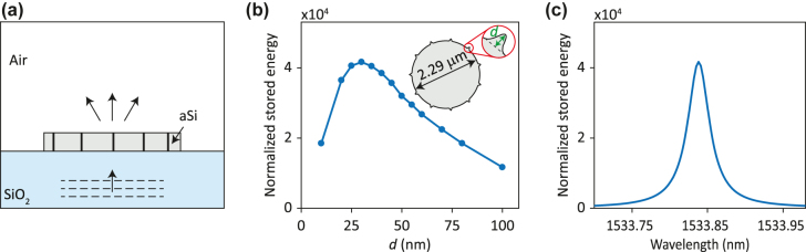
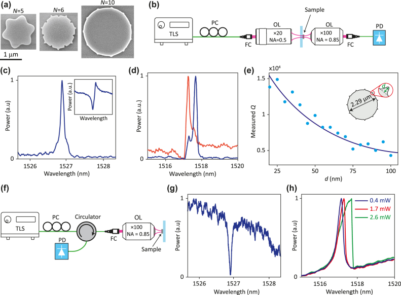
Optical microresonators with low quality factor ( Q ) can be efficiently excited by and scatter freely propagating optical waves, but those with high Q typically cannot. Here, we present a universal model for resonators interacting with freely propagating waves and show that the stored energy of a resonator excited by a plane wave is proportional to the product of its Q and directivity. Guided by this result, we devise a microdisk with periodic protrusions in its circumference that couples efficiently to normally incident plane waves. We experimentally demonstrate several microdisk designs, including one with a radius of 0.75 λ 0 and Q of 15,000. Our observation of thermally-induced bistability in this resonator at input powers as low as 0.7 mW confirms strong excitation. Their small footprints and mode volumes and the simplicity of their excitation and fabrication make wavelength-scale, free-space-coupled microdisks attractive for sensing, enhancing emission and nonlinearity, and as micro-laser cavities.

Keywords: flat optics; free space coupling; microresonators.


Figures

Figure 1:
Figure 1:
Excitation of free-space-coupled resonators. (a) Schematic illustration of a resonator with a quality factor Q illuminated and excited with a plane wave. The directivity pattern D(θ, ϕ) of the resonator, which is its normalized radiation pattern, is also shown. (b) Schematic of a microdisk resonator, a snapshot of the electric field squared of one of its resonant modes with azimuthal order N=10, and its radiation pattern. (c) The electric field of the resonant mode of a microdisk resonator. Small perturbations to the resonator are shown as small circles around the microdisk in the drawing on the left and can be represented by a polarization current density ΔJ as shown in the drawing on the right. (d) Resonant mode and radiation pattern of an FSC microdisk resonator for a mode with azimuthal order N = 10. There are N+1= 11 protrusions on the microdisk circumference. (e) Resonant modes and radiation patterns of two different FSC microdisk resonators for mode with azimuthal orders N = 5 and 6. There are N+1 = 6 and 7 protrusions on the microdisks’ circumferences. (f) The quality factor of the resonator shown in (d) as a function of the protrusion depth d.
Figure 2:
Figure 2:
Excitation of an FSC microdisk resonator by a plane wave. (a) Illustration of an FSC microdisk resonator excited by a normally incident plane wave. (b) Normalized stored energy Us/(uinλ03) as a function of the grating protrusion d at its resonant wavelength, and (c) as a function wavelength for d = 30 nm. The boundary of the microdisk is defined in polar coordinates according to ρ = R0+d(sin )n, where R0 = 1.145 µm, m = 5.5, and n = 100.
Figure 3:
Figure 3:
Exprimental results. (a) Scanning electron micrographs of fabricated FSC microdisk resonators with different azimuthal orders N. (b) Simplified schematic of the setup used for measuring transmission spectra of the resonators. (c) An example of a transmission spectrum of an FSC microdisk resonator. The inset shows another example of the observed transmission spectrum. (d) Measured transmission spectra of a resonator for two perpendicular linear polarizations of incident light. (e) Measured quality factors of FSC microdisks as a function of the protrusion depth d. The schematic of the resonator is shown in the inset. (f) Simplified schematic of the setup used for measuring reflection spectrum of FSC resonators. (g) Reflection spectrum of the resonator whose transmission spectrum is presented in (c). (h) Transmission spectra of an FSC resonator measured at different optical powers. TLS: tunable laser source, PC: polarization controller, OL: objective lens, FC: fiber coupler, PD: photodetector.

Similar articles

Cited by

  • Very-large-scale-integrated high quality factor nanoantenna pixels.
    Dolia V, Balch HB, Dagli S, Abdollahramezani S, Carr Delgado H, Moradifar P, Chang K, Stiber A, Safir F, Lawrence M, Hu J, Dionne JA. Dolia V, et al. Nat Nanotechnol. 2024 Sep;19(9):1290-1298. doi: 10.1038/s41565-024-01697-z. Epub 2024 Jul 3. Nat Nanotechnol. 2024. PMID: 38961248 Free PMC article.

References

    1. Yao Z., Wu K., Tan B. X., et al. Integrated silicon photonic microresonators: emerging technologies. IEEE J. Sel. Top. Quant. Electron. . 2018;24:1–24. doi: 10.1109/jstqe.2018.2846047. - DOI
    1. Wang C., Zhang M., Yu M., et al. Monolithic lithium niobate photonic circuits for Kerr frequency comb generation and modulation. Nat. Commun. . 2019;10:978. doi: 10.1038/s41467-019-08969-6. - DOI - PMC - PubMed
    1. Ellis B., Mayer M. A., Shambat G., et al. Ultralow-threshold electrically pumped quantum-dot photonic-crystal nanocavity laser. Nat. Photonics . 2011;5:297–300. doi: 10.1038/nphoton.2011.51. - DOI
    1. Decker M., Staude I., Falkner M., et al. High-efficiency dielectric Huygens’ surfaces. Adv. Opt. Mater. . 2015;3:813–820. doi: 10.1002/adom.201400584. - DOI
    1. Yu Y. F., Zhu A. Y., Paniagua-Dominguez R., et al. High-transmission dielectric metasurface with 2pi phase control at visible wavelengths. Laser Photon. Rev. . 2015;9:412–418. doi: 10.1002/lpor.201500041. - DOI

LinkOut - more resources