. 2023 Apr 4;12(10):1923-1930.
doi: 10.1515/nanoph-2023-0112. eCollection 2023 May.

Active 3D positioning and imaging modulated by single fringe projection with compact metasurface device

Affiliations

Active 3D positioning and imaging modulated by single fringe projection with compact metasurface device

Xiaoli Jing et al. Nanophotonics. .

Abstract

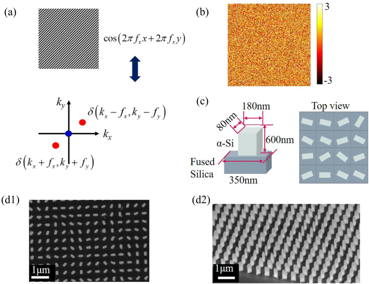
Three-dimensional (3D) information is vital for providing detailed features of the physical world, which is used in numerous applications such as industrial inspection, automatic navigation and identity authentication. However, the implementations of 3D imagers always rely on bulky optics. Metasurfaces, as the next-generation optics, shows flexible modulation abilities and excellent performance combined with computer vision algorithm. Here, we demonstrate an active 3D positioning and imaging method with large field of view (FOV) by single fringe projection based on metasurface and solve the accurate and robust calibration problem with the depth uncertainty of 4 μm. With a compact metasurface projector, the demonstrated method can achieve submillimeter positioning accuracy under the FOV of 88°, offering robust and fast 3D reconstruction of the texture-less scene due to the modulation characteristic of the fringe. Such scheme may accelerate prosperous engineering applications with the continued growth of flat-optics manufacturing process by using metadevices.

Keywords: depth sensing; geometric phase; metasurface.


Figures

Figure 1:
Figure 1:
Schematic of proposed method and principle of operation. (a) Experiment setup for 3D imaging system. (b) Calibration algorithm. The loss function of optimization algorithm is similarity evaluation, and the line constraint x i W = 0 denotes that the corresponding points x i of the certain pixel position x 0 i (red, blue, yellow, and green point in each calibrated image i) should be determined along a certain line (red, blue, yellow, and green point in the reference image) in the reference image. (c) Application of 3D positioning and imaging.
Figure 2:
Figure 2:
Metasurface design. (a) Functionality of fringe modulation. Depth information is embedded in the phase around the frequency component of modulated fringe. (b) Phase profile provided by metasurface. (c) Nanofin design. (d) SEM images. d1 and d2 are the top view and side view, respectively.
Figure 3:
Figure 3:
Calibration algorithm and results. (a) Epipolar geometry in the 3D imaging system. (b) The initial value of x i . The initial corresponding coordinate is estimated by finding the most similar points from the regions with proximal phase value in reference image. The orange line denotes the regions with proximal phase. (c) The goal of the calibration algorithm. The calibration aims to make each point x i have a high similarity with the corresponding calibrated image f i and stands in a line.
Figure 4:
Figure 4:
Calibration results and 3D positioning results. (a) Correlation values ZNSSD obtained by the optimized corresponding points. (b) Deviation values off the line calculated by the optimized corresponding points. (c) PV and RMS value calculated by the optimized corresponding points and look-up table. (d) Positioning results. The blue line represents the deviation values between the average value of reconstructed depth and the real depth value, and the bluish area is bounded by the maximum and minimal deviation of the depth distribution in each experiment. The orange line represents the RMS (root-mean-square) value of the depth distribution in each experiment.
Figure 5:
Figure 5:
3D facial imaging. (a) Captured image. (b) Wrapped phase. (c) Unwrapped phase. (d) Top view of 3D image. (e) Perspective view of 3D image.

References

    1. Wu Z., Guo W., Pan B., Kemao Q., Zhang Q. A DIC-assisted fringe projection profilometry for high-speed 3D shape, displacement and deformation measurement of textured surfaces. Opt. Las. Eng. 2021;142:106614. doi: 10.1016/j.optlaseng.2021.106614. - DOI
    1. Royo S., Ballesta-Garcia M. An overview of lidar imaging systems for autonomous vehicles. Appl. Sci. 2019;9:4093. doi: 10.3390/app9194093. - DOI
    1. Kaul L., Zlot R., Bosse M. Continuous-time three-dimensional mapping for micro aerical vehicles with a passively actuated rotating laser scanner. J. Field Robot. 2016;33:103–132. doi: 10.1002/rob.21614. - DOI
    1. Shamata A., Thompson T. Using structured light three-dimensional surface scanning on living individuals: key considerations and best practice for forensic medicine. J. Forensic Leg. Med. 2018;55:58–64. doi: 10.1016/j.jflm.2018.02.017. - DOI - PubMed
    1. Ham Y., Han K. K., Lin J. J., Goparvar-Fard M. Visual monitoring of civil infrastructure systems via camera-equipped unmanned aerial vehicles (UAVs): a review of related works. Visual. Eng. 2016;4:1–8. doi: 10.1186/s40327-015-0029-z. - DOI

LinkOut - more resources