. 2023 Oct 4;12(20):3931-3944.
doi: 10.1515/nanoph-2023-0392. eCollection 2023 Oct.

Multi-faceted plasmonic nanocavities

Affiliations

Multi-faceted plasmonic nanocavities

Kalun Bedingfield et al. Nanophotonics. .

Abstract

Plasmonic nanocavities form very robust sub-nanometer gaps between nanometallic structures and confine light within deep subwavelength volumes to enable unprecedented control of light-matter interactions. However, spherical nanoparticles acquire various polyhedral shapes during their synthesis, which has a significant impact in controlling many light-matter interactions, such as photocatalytic reactions. Here, we focus on nanoparticle-on-mirror nanocavities built from three polyhedral nanoparticles (cuboctahedron, rhombicuboctahedron, decahedron) that commonly occur during the synthesis. Their photonic modes have a very intricate and rich optical behaviour, both in the near- and far-field. Through a recombination technique, we obtain the total far-field produced by a molecule placed within these nanocavities, to reveal how energy couples in and out of the system. This work paves the way towards understanding and controlling light-matter interactions, such as photocatalytic reactions and non-linear vibrational pumping, in such extreme environments.

Keywords: crystallization facet; facet; nanocavity; nanogap; nanoparticle; quasi-normal modes.


Conflict of interest statement

Conflict of interest: Authors state no conflicts of interest.

Figures

Figure 1:
Figure 1:
Nanoparticle on mirror configurations (A) truncated spherical nanoparticle on mirror (TSoM) schematic for a gold NP of radius r p with a circular facet of diameter f d assembled a distance d above a flat gold substrate, separated by a spacer of refractive index n. Polyhedral NP structures above their corresponding scanning electron microscopy images: (B) cuboctahedron, (C) rhombicuboctahedron and (D) decahedron [39]. The green, red and blue facets refer to planes of gold atom crystallization {100}, {110} and {111}, respectively.
Figure 2:
Figure 2:
QNMs of the different nanoparticle-on-mirror structures, with the facet forming the nanocavity indicated in the second column. The geometries from top to bottom are the: circular facet of TSoM; two square and one triangular facets of RhoM; singular square and triangular facets of the CoM; and the triangular facet of NDoM. The modes from left to right are: (1,0), (1,1), (1,1), (2,2), (2,2), (2,0), where the colour corresponds to the normalised QNM electric fields (Re[E z,lm ]) on the xy-plane through the centre of their respective nanocavities.
Figure 3:
Figure 3:
Complex QNM eigenfrequencies represented as Lorentzians, showing their spectral arrangement and energetic ordering for the: circular facet of the TSoM; two square and one triangular facets of the RhoM; singular square and triangular facets of the CoM; and the triangular facet of the NDoM. The labels correspond to the nanocavity configuration as shown in Figure 2. Dashed lines represent degenerate QNMs. Vertical dashed lines mark the wavelengths of (dark green) 775 nm and (light green) 900 nm.
Figure 4:
Figure 4:
Far-field emission for the QNMs of the different particle-on-mirror structures, with the facet forming the nanocavity indicated in the second column. The geometries from top to bottom: circular facet of the TSoM; two square and one triangular facets of the RhoM; singular square and triangular facets of the CoM; and the triangular facet of the NDoM. The modes from left to right: (1,0), (1,1), (1,1), (2,2), (2,2), (2,0), where the colour corresponds to the normalised time averaged Poynting flux ⟨S lm ⟩. White dashed lines are added over the (1,1) modes to highlight the correspondence of their direction and orthogonality with their near-field counterparts (i.e. normal to each other).
Figure 5:
Figure 5:
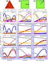
α-coefficients of the polyhedral NPoM geometries, for a series of emitter positions within the nanocavities. Column A – The triangular facets of the polyhedral systems, following a path from perpendicular line drawn from one of the facet edges to the opposite corner, through the triangular facet centroid—normalised to the total length of this parth (h=3a/2) . Column B – The square facets of the polyhedral systems, following a path along the x-axis from the centre of the facet. Column C – The square facets of the polyhedral systems, following a path along the diagonal from the centre of the facet. White and blue backgrounds, respectively, correspond to emitter transition wavelengths of λ em = 775 nm and λ em = 900 nm.
Figure 6:
Figure 6:
Reconstructed total far-field emission of the different particle-on-mirror structures, for a series of emitter positions within the nanocavities. The geometries are the CoM, NDoM and RhoM structures assembled on their triangular facets, with the colour corresponding to the normalised time averaged total Poynting flux ⟨S tot ⟩. The emitter positions follow a path P from the perpendicular line drawn from one of the facet edges to the opposite corner of the triangle facet, through its centroid—and is shown normalised to the length of this path (h=3a/2) . White and blue backgrounds respectively correspond to emitter transition wavelengths of λ em = 775 nm and λ em = 900 nm, and the dark red border represents the relative rounding region of the facet edge with respect to the facet size (i.e. ρ/a) of each nanocavity.
Figure 7:
Figure 7:
Reconstructed total far-field emission of the different particle-on-mirror structures, for a series of emitter positions within the nanocavities. The geometries are the CoM and RhoM structures assembled on their square facets, with the colour corresponding to the normalised time averaged total Poynting flux ⟨S tot ⟩. For each structure, two emitter paths are considered: one from the centre of the facet to the edge, along the x-axis; and the other from the centre of the facet to the corner, along the diagonal. White and blue backgrounds, respectively correspond to emitter transition wavelengths of λ em = 775 nm and λ em = 900 nm.

References

    1. Mertens J., Eiden A. L., Sigle D. O., et al. Controlling subnanometer gaps in plasmonic dimers using graphene. Nano Lett. . 2013;13(11):5033–5038. doi: 10.1021/nl4018463. - DOI - PubMed
    1. Thacker V. V., Herrmann L. O., Sigle D. O., et al. DNA origami based assembly of gold nanoparticle dimers for surface-enhanced Raman scattering. Nat. Commun. . 2014;5 3448. - PubMed
    1. Benz F., Tserkezis C., Herrmann L. O., et al. Nanooptics of molecular-shunted plasmonic nanojunctions. Nano Lett. . 2015;15(1):669–674. doi: 10.1021/nl5041786. - DOI - PMC - PubMed
    1. de Nijs B., Bowman R. W., Herrmann L. O., et al. Unfolding the contents of sub-nm plasmonic gaps using normalising plasmon resonance spectroscopy. Faraday Discuss. 2015;178:185–193. doi: 10.1039/c4fd00195h. - DOI - PubMed
    1. Sigle D. O., Mertens J., Herrmann L. O., et al. Monitoring morphological changes in 2D monolayer semiconductors using atom-thick plasmonic nanocavities. ACS Nano . 2015;9(1):825–830. doi: 10.1021/nn5064198. - DOI - PMC - PubMed

LinkOut - more resources