Review
. 2024;220(8):91.
doi: 10.1007/s11214-024-01115-9. Epub 2024 Dec 4.

The Europa Imaging System (EIS) Investigation

Affiliations
Review

The Europa Imaging System (EIS) Investigation

E P Turtle et al. Space Sci Rev. 2024.

Abstract

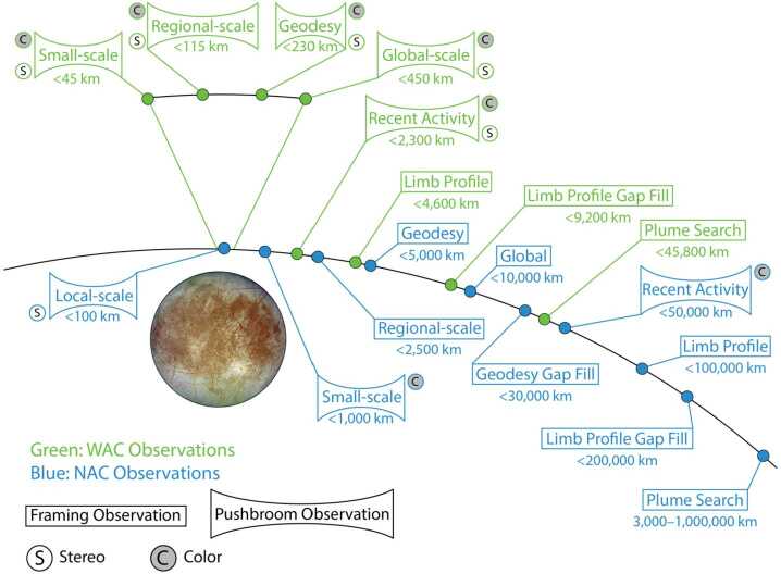
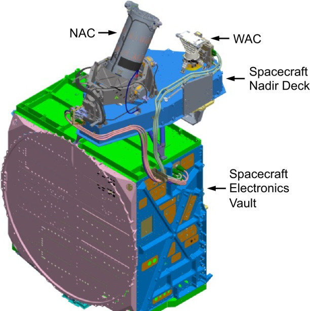
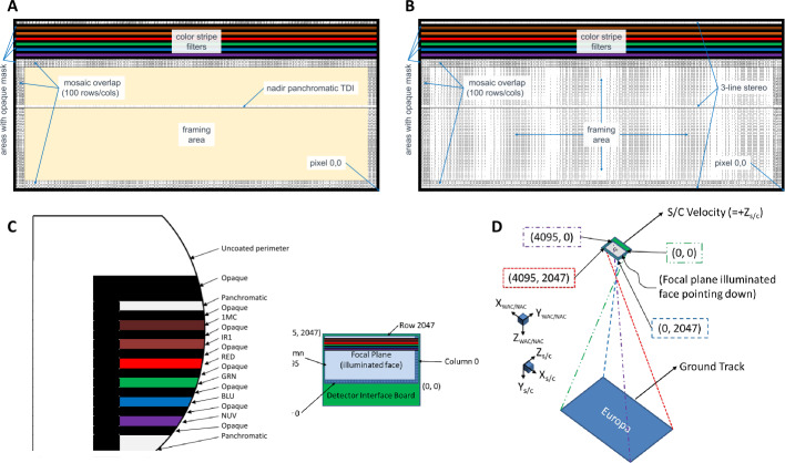
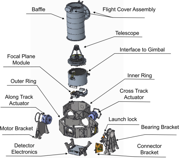
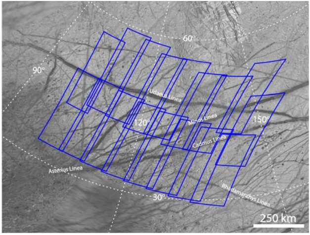
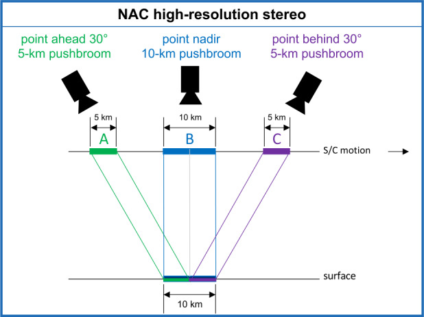
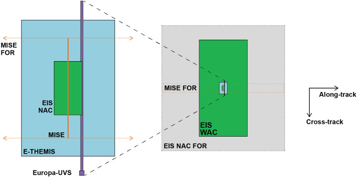
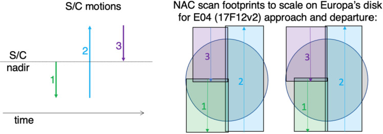
The Europa Imaging System (EIS) consists of a Narrow-Angle Camera (NAC) and a Wide-Angle Camera (WAC) that are designed to work together to address high-priority science objectives regarding Europa's geology, composition, and the nature of its ice shell. EIS accommodates variable geometry and illumination during rapid, low-altitude flybys with both framing and pushbroom imaging capability using rapid-readout, 8-megapixel (4k × 2k) detectors. Color observations are acquired using pushbroom imaging with up to six broadband filters. The data processing units (DPUs) perform digital time delay integration (TDI) to enhance signal-to-noise ratios and use readout strategies to measure and correct spacecraft jitter. The NAC has a 2.3° × 1.2° field of view (FOV) with a 10-μrad instantaneous FOV (IFOV), thus achieving 0.5-m pixel scale over a swath that is 2 km wide and several km long from a range of 50 km. The NAC is mounted on a 2-axis gimbal, ±30° cross- and along-track, that enables independent targeting and near-global (≥90%) mapping of Europa at ≤100-m pixel scale (to date, only ∼15% of Europa has been imaged at ≤900 m/pixel), as well as stereo imaging from as close as 50-km altitude to generate digital terrain models (DTMs) with ≤4-m ground sample distance (GSD) and ≤0.5-m vertical precision. The NAC will also perform observations at long range to search for potential erupting plumes, achieving 10-km pixel scale at a distance of one million kilometers. The WAC has a 48° × 24° FOV with a 218-μrad IFOV, achieving 11-m pixel scale at the center of a 44-km-wide swath from a range of 50 km, and generating DTMs with 32-m GSD and ≤4-m vertical precision. The WAC is designed to acquire three-line pushbroom stereo and color swaths along flyby ground-tracks.

Keywords: Camera; Europa; Europa Clipper Mission; Icy satellite; Mapping; Ocean world; Plumes.


Conflict of interest statement

Competing InterestsThe authors have no competing interests to declare that are relevant to the content of this article.

Figures

Fig. 1
Fig. 1
EIS datasets. Sequence of observation types during a flyby as a function of range to Europa. Although only shown once here for clarity, observations are made both inbound and outbound depending on illumination. (Not to scale)
Fig. 2
Fig. 2
EIS panchromatic and color-filter system transmission for NAC (solid lines) and WAC (dashed lines). NAC NUV is derived from component-level measurement. WAC NUV is not shown here due to very low transmission at these wavelengths through the WAC optics. The periodic nature of the NAC transmission is related to the anti-reflection coatings
Fig. 3
Fig. 3
Configuration of the NAC and WAC, spacecraft nadir deck, harnesses (NAC harness in pink and WAC in green), and electronics vault with additional radiation shielding. The NAC is shown with the gimbal in the launch orientation (Sect. 3.4.1)
Fig. 4
Fig. 4
EIS NAC and WAC filter layouts and imaging applications for (A) NAC and (B) WAC, with (C) zoom view of color filters and opaque masking. The filter stripes and the opaque masks between them are each 32-rows wide. (D) shows the detector orientation on the spacecraft. (Transmission through the color filters is shown in Fig. 2)
Fig. 5
Fig. 5
NAC expanded diagram (top) and assembled flight hardware (bottom)
Fig. 5
Fig. 5
NAC expanded diagram (top) and assembled flight hardware (bottom)
Fig. 6
Fig. 6
Gimbal bearings, PCS, and hard stops
Fig. 7
Fig. 7
Schematic illustration of the NAC telescope
Fig. 8
Fig. 8
WAC expanded diagram (top) and assembled flight hardware (bottom)
Fig. 9
Fig. 9
Schematic illustration of the WAC telescope
Fig. 10
Fig. 10
Example layout of a mosaic of NAC frames
Fig. 11
Fig. 11
Schematic of WAC imaging swath (green) showing planned mapping sections with standard scales of 5, 10, 20, 40, 80, 160, and 320 m/pixel. The data are oversampled by no more than 2× and file sizes are reasonable. The map sections are easily re-sized to combine into larger-scale mosaics
Fig. 12
Fig. 12
Illustration of WAC three-line pushbroom stereo with 12° convergence angle between forward, nadir, and aft lines to achieve ∼4-m vertical precision over 32-m GSD from 50-km altitude
Fig. 13
Fig. 13
Illustration of the NAC along-track pushbroom stereo sequence at an altitude of 50 km: the NAC is targeted 30° forward to acquire a 5-km-long pushbroom image; the NAC is then targeted nadir to acquire a 10-km-long pushbroom image, half of which overlaps with the forward image; finally, the NAC is targeted 30° aft to acquire a 5-km-long pushbroom image that overlaps with the second half of the nadir image. The three images combine to make two 5-km-long stereo pairs that will be used to generate a DTM with a GSD of 4 m and a vertical precision of ≤0.5 m
Fig. 14
Fig. 14
Schematic of the relative footprint sizes and boresight alignment for the Europa Clipper optical remote sensing instruments. Pushbroom imaging by EIS, Europa-UVS, E-THEMIS, and MISE enables variable along-track image lengths. The NAC field of regard (FOR) is enabled by the ±30° along- and cross-track gimbals. The MISE FOR is enabled by a ±30° scan mirror
Fig. 15
Fig. 15
NAC can cover nearly the full disk of Europa at 25,000–40,000 km range for the joint scans with other remote-sensing instruments by using gimbal pointing to offset the FOV during 1) the initial spacecraft slew to point off the edge of the disk of Europa, 2) the constant-rate spacecraft scan across Europa, and 3) the spacecraft slew back to the center of Europa’s disk. Scans 1 and 3 have non-constant velocity, so image segments may be needed to change line time. (The example geometry is based on an earlier but similar version of the trajectory: 17F12_V2)
Fig. 16
Fig. 16
Map of limb profiles observed by NAC and WAC in the baseline tour, 21F31_V6 (Pappalardo et al. , this collection), at scales from 0.4 to 1 km/pixel, which are near ideal because the limb can be covered in a single image or small mosaics. The gaps near the apex and antapex of orbital motion can be filled in to some degree at lower resolution

References

    1. Abrahams JNH, Nimmo F, Becker TM, Gladstone GR, Retherford KD, Steinbrügge G, Mazarico E (2021) Improved determination of Europa’s long-wavelength topography using stellar occultations. Earth Space Sci 8(7):e2020EA001586. 10.1029/2020EA001586
    1. Archinal BA, Acton CH, A’Hearn MF, Conrad A, Consolmagno GJ, Duxbury T, Hestroffer D, Hilton JL, Kirk RL, Klioner SA, McCarthy D, Meech K, Oberst J, Ping J, Seidelmann PK, Tholen DJ, Thomas PC, Williams IP (2018) Report of the IAU working group on cartographic coordinates and rotational elements: 2015. Celest Mech Dyn Astron 130(3):22. 10.1007/s10569-017-9805-5
    1. Bart GD (2014) The quantitative relationship between small impact crater morphology and regolith depth. Icarus 235:130–135. 10.1016/j.icarus.2014.03.020
    1. Becker KJ, Brent A, Hare T, Kirk RL, Howington-Kraus E, Robinson M, Rosiek M (2015) Criteria for automated identification of stereo pairs. In: 46th Lunar and Planetary Science Conference, p 2703
    1. Becker HN, Lunine JI, Schenk PM, Florence MM, Brennan MJ, Hansen CJ, et al. (2023) A complex region of Europa’s surface with hints of recent activity revealed by Juno’s Stellar Reference Unit. J Geophys Res, Planets 128:e2023JE008105. 10.1029/2023JE008105

LinkOut - more resources