

A microgripper based on electrothermal Al-SiO2 bimorphs
- PMID: 39681569
- PMCID: PMC11649916
- DOI: 10.1038/s41378-024-00821-2
A microgripper based on electrothermal Al-SiO2 bimorphs
Abstract
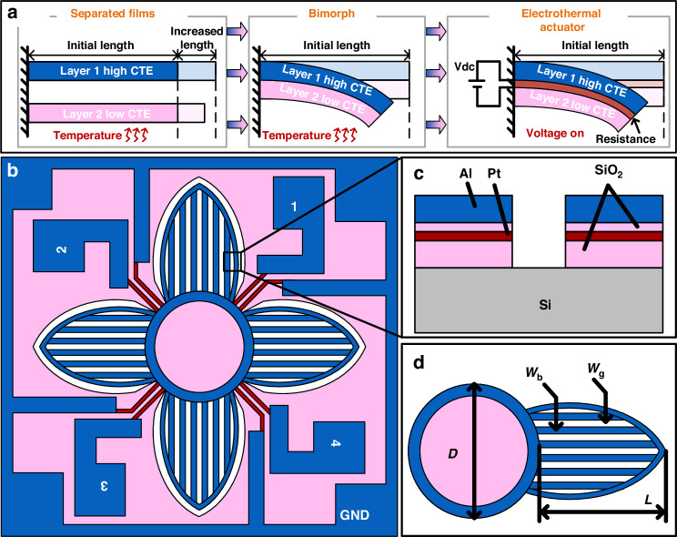
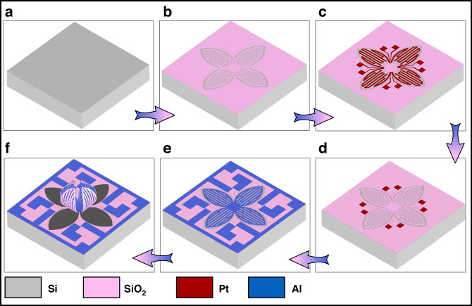
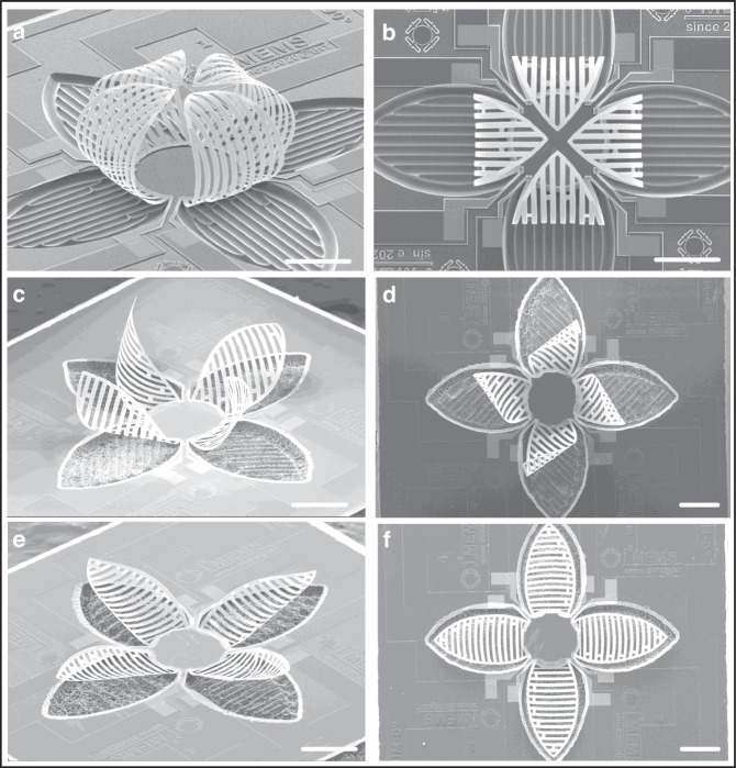
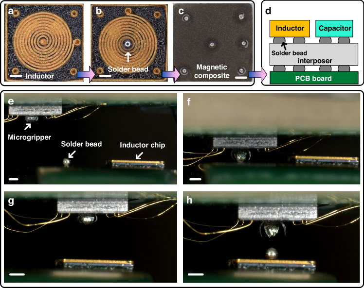
Microgrippers are essential for assembly and manipulation at the micro- and nano-scales, facilitating important applications in microelectronics, MEMS, and biomedical engineering. To guarantee the safe handling of delicate materials and micro-objects, a microgripper needs to be designed to operate with exceptional precision, rapid response, user-friendly operation, strong reliability, and low power consumption. In this study, we develop an electrothermal actuated microgripper with Al-SiO2 bimorphs as the primary structural element. The fabricated microgripper naturally adopts a closed state due to process-induced residual stresses. The thermal expansion mismatch between Al and SiO2 allows for an easy transition of the microgripper between open and closed states by temperature control. Experimental data reveal that the microgripper can achieve impressive deformability, bending over 100 degrees at just 5 V, and responding within 10 ms. Its capability to handle micro-objects is verified using polymethyl methacrylate (PMMA) microbeads and its gripping strength is quantitatively assessed. It is demonstrated that the microgripper holding a microbead with a diameter of 400 μm and a weight of 0.1 mg can withstand an average acceleration of 35 g during vibration test and over 1600 g in impact tests, highlighting its exceptional grasping performance. Additionally, the "pick-and-place" task for handling and positioning solder beads (0.25 mg for each bead) with diameters of 400 μm on a bulk silicon inductor chip has been successfully completed. This unique microgripper is anticipated to be highly beneficial for various micro-assembly and micromanipulation applications, particularly in the field of electronic packaging.
© 2024. The Author(s).
Conflict of interest statement
Conflict of interest: The authors declare no competing interests.
Figures


References
-
- Diller, E. & Sitti, M. Three-dimensional programmable assembly by untethered magnetic robotic micro-grippers. Adv. Funct. Mater.24, 4397–4404 (2014). - DOI
Grants and funding
- 62350710218/National Natural Science Foundation of China (National Science Foundation of China)
- 62204013/National Natural Science Foundation of China (National Science Foundation of China)
- 62204013/National Natural Science Foundation of China (National Science Foundation of China)
- 62074015/National Natural Science Foundation of China (National Science Foundation of China)
- 62102050/National Natural Science Foundation of China (National Science Foundation of China)
LinkOut - more resources
Full Text Sources