Review
. 2024 Nov 22;25(23):12567.
doi: 10.3390/ijms252312567.

Photocrosslinkable Biomaterials for 3D Bioprinting: Mechanisms, Recent Advances, and Future Prospects

Affiliations
Review

Photocrosslinkable Biomaterials for 3D Bioprinting: Mechanisms, Recent Advances, and Future Prospects

Yushang Lai et al. Int J Mol Sci. .

Abstract

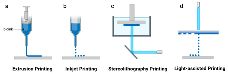
Constructing scaffolds with the desired structures and functions is one of the main goals of tissue engineering. Three-dimensional (3D) bioprinting is a promising technology that enables the personalized fabrication of devices with regulated biological and mechanical characteristics similar to natural tissues/organs. To date, 3D bioprinting has been widely explored for biomedical applications like tissue engineering, drug delivery, drug screening, and in vitro disease model construction. Among different bioinks, photocrosslinkable bioinks have emerged as a powerful choice for the advanced fabrication of 3D devices, with fast crosslinking speed, high resolution, and great print fidelity. The photocrosslinkable biomaterials used for light-based 3D printing play a pivotal role in the fabrication of functional constructs. Herein, this review outlines the general 3D bioprinting approaches related to photocrosslinkable biomaterials, including extrusion-based printing, inkjet printing, stereolithography printing, and laser-assisted printing. Further, the mechanisms, advantages, and limitations of photopolymerization and photoinitiators are discussed. Next, recent advances in natural and synthetic photocrosslinkable biomaterials used for 3D bioprinting are highlighted. Finally, the challenges and future perspectives of photocrosslinkable bioinks and bioprinting approaches are envisaged.

Keywords: 3D bioprinting; hydrogel; photocrosslinkable biomaterials.


Conflict of interest statement

The authors declare no conflicts of interest.

Figures

Figure 5
Figure 5
Collagen-based photocrosslinking bioinks. (a) Schematic representation of methacrylate- [171,172], maleic- [173], norbornene- [170], and thiol-modified [174] collagen synthesis. (b) The relative solubility of NorCol and collagen at different pH values. (c) The miscibility of NorCol with gelatin and alginate. (d) Temperature-sensitive extrusion bioprinting of NorCol bioinks. (d) (i) Schematic of temperature-sensitive extrusion bioprinting of NorCol bio-inks. (ii) Printed NorCol hydrogels (12 layers, 3 mm) after 1 day of culture. Fluorescence micrographs showing cell (iii) viability (day 1) and (iv) spreading (day 5) within NorCol hydrogels (Copyright 2021 American Chemical Society [170]).
Figure 8
Figure 8
Hyaluronic acid-based photocrosslinking bioinks. (a) Synthesis route of light-cured hyaluronic acid. (b) Modification of sodium HA with CA to form NorHACA. (i) Reaction scheme for NorHACA synthesis. (ii) Degree of modification of HA with norbornene is tuned by changing the molar ratio of CA to HA repeat units. (iii) Schematic representation of network formation by visible light-induced thiol-ene step-growth reaction between NorHACA and DTT in the presence of photoinitiator (LAP), (** p < 0.01, **** p < 0.0001). (c) Biocompatibility and DLP-based 3D bioprinting of NorHACA bioinks. (i) Representative fluorescence micrographs of bMSCs encapsulated in NorHACA (5wt%, 40%mod.) bulk hydrogels over time (1, 3, and 7 days), scale bars = 200 μm. (ii) Semiquantitative analysis of cell viability, (* p < 0.05). (iii) Schematic representation of DLP-based 3D printing of NorHACA hydrogels with bMSCs. (iv) Representative maximum projection image of bMSCs encapsulated in a NorHACA macroporous lattice at day 1, scale bars = 1 mm and 500 μm (Copyright 2023 American Chemical Society [204]). (d) HA-TBA mediates the synthesis of NorHA.
Figure 10
Figure 10
SF-based photocrosslinkable bioink. (a) Production, structure, and modification of SF (Copyright 2023 Elsevier [228]). (b) The design and printing performance of the redox-crosslinkable SF/CG bioink. (i) Schematic of the printing process of SF/CG bioink. (ii) CAD images depicting the ear, nose, and hand and printed images at various angles (Copyright 2024 Elsevier [237]). (c) Methacrylate-group-functionalized SF for recapitulating human skin models through 3D bioprinting (Copyright 2024 Wiely [243]).
Figure 1
Figure 1
Schematic illustration of (a) extrusion, (b) inkjet, (c) stereolithography, and (d) light-assisted 3D bioprinting (The figures were created with BioRender).
Figure 2
Figure 2
A schematic illustration of the mechanism of free radical chain-growth polymerization. (a) The mechanism of free radical chain-growth polymerization. (b) A schematic of polymer chains containing reactive groups crosslinking through free radical chain-growth polymerization.
Figure 3
Figure 3
Schematic illustrations of the mechanism of thiol-ene-mediated polymerization. (a) A schematic illustration of the mechanism of thiol-ene crosslinking. (b) A schematic of polymer chains containing reactive groups crosslinking through thiol-ene polymerization. (c) Kinetic modeling of photoinitiated thiol-ene click chemistry based on alkene conversion and a summary of the reactivity of the alkene group (Copyright 2012 American Chemical Society [122]).
Figure 4
Figure 4
The mechanism of redox crosslinking. (a) A schematic illustration of the mechanism of redox polymerization. (b) A schematic of polymer chains containing reactive groups crosslinking through redox reactions.
Scheme 1
Scheme 1
Radical generation mechanisms of type I and type II photoinitiators. * means exciting state.
Figure 6
Figure 6
Schematic illustration of collagen hydrolysis and representative routes to synthesize methacrylate, norbornene, vinyl, and tyrosine-modified gelatin.
Figure 7
Figure 7
The bioprinting performance of photocrosslinkable gelatin bioinks. (a) The cell viability within the printed scaffold is affected by the methacrylate degree of GelMA. (i) Photocrosslinking for solidification. (ii) Evaluation of live and dead cells encapsulating in 7.5% GM-30/60/90 on day 5. (iii) Semiquantitative analysis of cell viability, (** p < 0.01, *** p < 0.001) (Copyright 2023 Wiley [52]). (b) An illustrative scheme of cell-laden bioprinting using GelMA and GelNB/HepSH bioinks. (c) HUVEC-laden constructs are built from GelNB/HepSH and GelMA bioinks. (i) Fluorescence micrographs showing the bioprinted constructs after 1 and 7 days of culture. (ii) Semiquantitative analysis of cell viability. Fluorescence micrographs showing HUVEC cytoskeleton in both bioinks after cell culture for 7 days, using (iii) an inverted fluorescence microscope and (iv) a laser scanning confocal microscope, scale bars = 500 μm. (v,vi) 3D-printed canine peripheral-nerve-like constructs using the GelNB/HepSH bioink, scale bars = 4 mm (Copyright 2021 American Chemical Society [112]). (d) GelNB/GelS bioinks can undergo superfast gelation at extremely low photoinitiator concentrations. (i) Water-based synthesis of GelNB and GelS from gelatin. (ii) Photocrosslinked thiol-ene click hydrogel. (iii) Comparison of the two thiol-ene hydrogel systems GelNB/DTT and GelNB/GelS. *** p < 0.001. (e) The 3D bioprinting of an NHDF-laden hydrogel grid structure (i) 3D bioprinting of a hydrogel grid structure (1 cm × 1 cm) consisting of four layers on a glass slide. Post-printing cell viability analysis of 3D bioprinted NHDF at day 1 using (ii) GelMA and (iii) GelNB/GelS bioinks. (iv) Distribution of NHDF within the hydrogel, (i) Live/dead staining and (ii) distribution of NHDF, scale bars = 100 μm, (** p < 0.01) (Copyright 2021 Wiley [180]). (f) A schematic comparison of GelNB synthesized by (i) 5-norbornene-2-carboxylic acid and (ii) CA.
Figure 9
Figure 9
Alginate-based bioinks. (a) The (i) structure and (ii) gelation mechanism of alginate. (b) The norbornene alginate bioink (Alg-norb) was functionalized by light-mediated RGD grafting for building L929 cell-embedded constructs. (i) Schematic overview of the strategy employed to develop photoactive Alg-norb for bioprinting. (ii) Photoinitiated thiol−ene reactions of Alg-norb with RGD Peptide Sequence (CGGGRGDS). (iii) Images of 3D bioprinted hydrogels loaded with cells at (a) day 0 and (b) day 7. Green and red cell tracker labeled L929 as two different bioinks printed as alternating fibers (c) in the X-Y plane and (d) in the Z direction (Copyright 2018 American Chemical Society [218]). (c) The synthesis of Alg-RGD through a thiol-ene click reaction to promote the cell growth and vascularization of HUVECs. (i) Design of the HA/Alg-RGD hydrogel. (ii) Schematic diagram of the 3D printing process. (iii) Fluorescent images of GFP-HUVECs cultured in the hydrogel at intervals of 3, 7, and 14 days post-3D printing, along with magnified images of selected regions (scale bar = 1 mm and 200 μm, respectively) (Copyright 2023 American Chemical Society [219]).
Figure 11
Figure 11
dECM-based photocrosslinkable bioinks. (a) The production and modification of dECM (Copyright 2023 Ivyspring [252]). (b) The Ru/SPS-induced visible light crosslinking of dECM. (i) The crosslinking mechanism. (ii) The gelled dECM hydrogel (Copyright 2023 Wiely [253]). (c) The light-activated dityrosine crosslinking reaction in dECM bioink to realize centimeter-scale 3D bioprinting. (i) A schematic of visible-light active dityrosine synthesis. (ii) Extrusion-based printing of dECM. (iii) DLP photopatterning with 100 µm step-size constructs, scale bars = 100 μm for white represent printed fiber, 500 μm for live/dead images, (Copyright 2021 Wiely [124]). (d) Liver dECM was functionalized by glycidyl methacrylate and methacrylic anhydride for the systematic comparison of different type of methacrylate dECM bioinks. The (i) preparation and (ii) modification of live dECM (Copyright 2024 Elsevier [254]). (e) The decellularized small intestine submucosa (dSIS) was functionalized by norbornene to create an orthogonally crosslinked dSIS hydrogel for cancer and vascular tissue engineering. (i) 1H NMR spectra of dSIS and dSIS-NB. Peak a: alkene protons (HC=CH), Peak b: ethyl protons (CH2), Peaks c and d: methine protons (C3CH). (ii) Schematic of thiol-norbornene photo-crosslinking. (iii) Schematic of DLP bioprinting. (iv) In situ, photo rheometry of dSIS-NB gelation with tartrazine added as a photo absorber to improve printing fidelity, dotted line indicate light on. (v) A CAD image of astar-shaped object for DLP bioprinting and the DLP printed dSIS-NB gel. (vi) A representative live/dead confocal image of interconnected microvascular HUVEC network within the printed hydrogel on day 3 (Copyright 2024 Wiely [255]).
Figure 12
Figure 12
PEG-based photocrosslinkable bioinks. (a) A schematic of the structures of modified photocrosslinkable PEG derivatives for 3D bioprinting. (b) A schematic diagram of the process for preparing a hydrogel with cell adhesion properties. (A) Schematic representation of the ink design and the hydrogel manufacturing process. (B) Synthetic approach toward labelled RGD peptides (Copyright 2024 Wiley [266]). (c) A schematic illustration of the fabrication of enzymatically degradable PEG hydrogels to mimic matrix remodeling. (A) Components used in the development of the bioinspired pseudo-reversible stiffening and softening hydrogels include PEG-4-Nb (Mn∼ 5, 10, or 20 kDa), PEG-8-Nb (Mn∼40 kDa), di-thiol nondegradable linkers (PEG-2-SH; Mn∼ 2 or 3.4 kDa), di-thiol MMP degradable linker, a di-thiol MMP PEG-conjugate (PEG8MMP), and an MMP-thrombin degradable peptide linker (MMP+Thb). (B) Hydrogel tools were designed to mimic aspects of matrix degradation or matrix deposition that occurs during matrix remodeling of the cellular microenvironment through incorporation of PEG8MMP and MMP+Thb linkers, respectively. (C) A reduction of matrix density was achieved by photopolymerization of PEG hydrogels in the presence of a combination of MMP and MMP+Thb linkers, enabling triggered softening through a reduction of crosslink density upon incubation with thrombin. (D) For triggered stiffening, hydrogels were formed by photopolymerization of PEG hydrogels in the presence of MMP crosslinkers followed by secondary photopolymerization of excess reactive handles with PEG or peptide linkers (Copyright 2022 Wiley [267]). (d) A schematic representation of MSN bioinks for extrusion-based in situ bioprinting applications (Copyright 2023 Elsevier [268]).
Figure 13
Figure 13
PF127 and PVA for 3D bioprinting. (a) A schematic diagram of the structure and gel formation mechanism of PF127 (Copyright 2020 American Chemical Society [283]). (b) A schematic diagram of PF127 as a sacrificial material for the preparation of microvascular tissue. (i) Schematic of the manufacturing process. (ii) Perfusion of fluorescent dextran solution into a GFP-HDFs/RFP-HUVECs co-culture construct (Copyright 2021 IOP Publishing [282]). (c) Norbornene-modified PVA and gelatin were used to construct a cell-laden hydrogel through volumetric bioprinting (VBP) to promote cell growth and support osteogenic differentiation. (i) (a) Schematic of the set-up for VBP. (b) Illustration of VBP of a PVA bioresin. (c) Chemical structures of norbornene-modified PVA, thiolated crosslinker (PEG2SH), and photoinitiator (LAP). (d) Mechanism of radical-mediated thiol-norbornene photoclick reaction. (ii) (a) Live(green)/dead(red) stained hMSCs following 24 h after printing, scale bars = 100 µm (i, iv). Confocal images of actin-nuclei stained hMSCs in soft and stiff gels at 24 h (ii, v) and 7 days (iii, vi) after printing, scale bars = 100 µm (ii, v) and 50 µm (iii, vi). Scale bars for all inserts are 20 µm. Visualization of single cells in soft and stiff matrix using automated IMARIS dendrite tracking, scale bars = 10µm (iii-1, vi-1). (b) Quantification of cell viability of hMSCs at different time points. (c) Quantification of average cell area in soft and stiff constructs over time. (* p = 0.0485; ns, not significant; n ≥ 3) (d) Confocal image of actin-nuclei stained hMSCs showing cell-cell contacts in the soft gels following 14 days of osteogenic culture (Copyright 2023 Wiley [284]).
Figure 14
Figure 14
Representative photoinitiator-free photocrosslinking strategies. (a) A schematic diagram of UV light crosslinking based on coumarin derivatives. (b) A schematic diagram of UV-light-triggered imine crosslinking (Copyright 2021 American Association for the Advancement of Science [337]). (c) A schematic diagram of UV-light-mediated dual crosslinking based on azide-modified chitosan (Copyright 2011 American Chemical Society [335]). (d) A schematic diagram of photoinitiator-free photocrosslinking with SbQ as an intermediate. (i) Synthesis of PVA-SBQ and (ii) UV-light-mediated crosslinking mechanism.
Figure 15
Figure 15
The application of NIR-light-mediated photocrosslinking based on upconversion nanoparticles (UCNPs) for in vivo 3D bioprinting. (a) NIR photopolymerization-based 3D printing technology that enables the noninvasive in vivo 3D bioprinting of tissue constructs (Copyright 2020 American Association for the Advancement of Science [340]). (b) The 3D bioprinting of noninvasive fracture scaffolds in vivo by the NIR photocuring method. (i) Schematic of the noninvasive fixation of a broken bone with the UCNPs-assisted 3D bioprinting in-vivo. (ii) Fixation scaffolds for (a) oblique and (b) comminuted fractures using UCNPs-assisted NIR 3Dprinting. Images (I, II, III, and IV) show the pre-fracture, post-fracture, 3D skeleton fixation, and corresponding magnified images of the bones respectively. The shin bones of chickens were used in the experiment, scale bar = 0.65 cm. (c) Photograph and CT image with a broken rat. (d) Bioink is subcutaneously injected into the fracture area. (e) 3D in-vivo printing. (f) Images of fracture fixation positions in-vivo, scale bar = 0.6 cm (Copyright 2024 Wiley [339]).

Similar articles

Cited by

References

    1. Caprio N.D., Davidson M.D., Daly A.C., Burdick J.A. Injectable MSC Spheroid and Microgel Granular Composites for Engineering Tissue. Adv. Mater. 2024;36:e2312226. doi: 10.1002/adma.202312226. - DOI - PMC - PubMed
    1. Qiu C., Sun Y., Li J., Zhou J., Xu Y., Qiu C., Yu K., Liu J., Jiang Y., Cui W., et al. A 3D-Printed Dual Driving Forces Scaffold with Self-Promoted Cell Absorption for Spinal Cord Injury Repair. Adv. Sci. 2023;10:e2301639. doi: 10.1002/advs.202301639. - DOI - PMC - PubMed
    1. Wu X., Zhu H., Song C., Tan Q., Zhao Y., Shang L. Breadmaking-Inspired Antioxidant Porous Yeast Microcarriers for Stem Cell Delivery in Diabetic Wound Treatment. Adv. Mater. 2024;36:e2309719. doi: 10.1002/adma.202309719. - DOI - PubMed
    1. Masri S., Zawani M., Zulkiflee I., Salleh A., Fadilah N.I.M., Maarof M., Wen A.P.Y., Duman F., Tabata Y., Abd Aziz I., et al. Cellular Interaction of Human Skin Cells towards Natural Bioink via 3D-Bioprinting Technologies for Chronic Wound: A Comprehensive Review. Int. J. Mol. Sci. 2022;23:476. doi: 10.3390/ijms23010476. - DOI - PMC - PubMed
    1. Zhou Z., Liu J., Xiong T., Liu Y., Tuan R.S., Li Z.A. Engineering Innervated Musculoskeletal Tissues for Regenerative Orthopedics and Disease Modeling. Small. 2024;20:e2310614. doi: 10.1002/smll.202310614. - DOI - PubMed

Substances

LinkOut - more resources