Review
. 2024 Dec 18;19(1):208.
doi: 10.1186/s11671-024-04087-5.

Opportunities for nanomaterials in more sustainable aviation

Affiliations
Review

Opportunities for nanomaterials in more sustainable aviation

Afshin Pendashteh et al. Discov Nano. .

Abstract

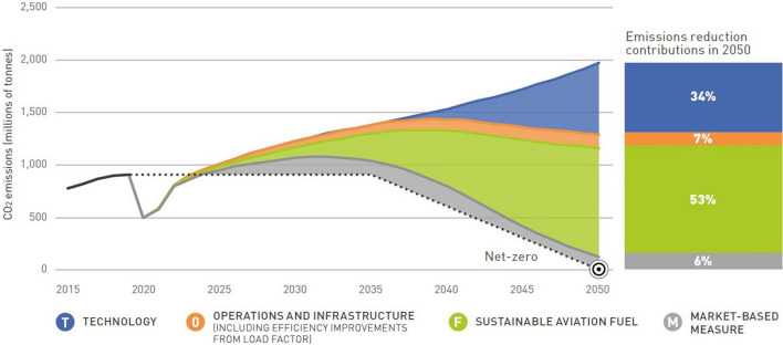
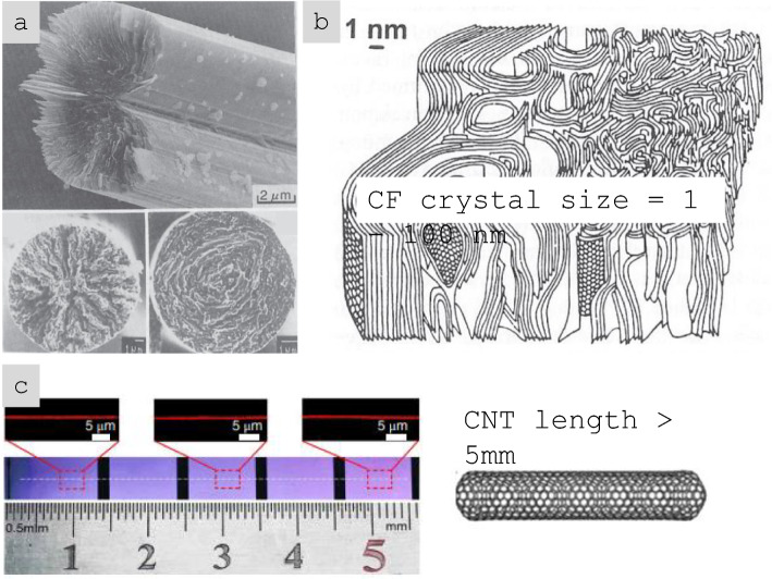
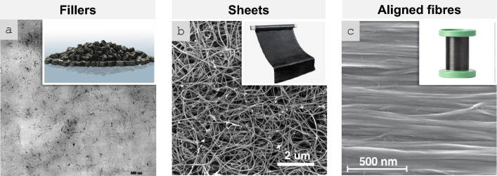
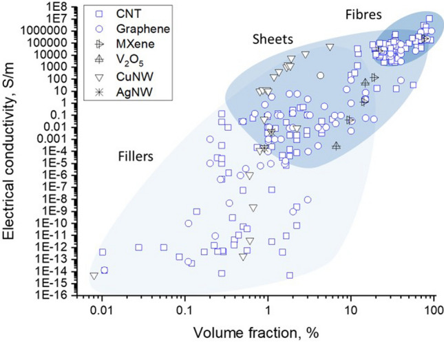
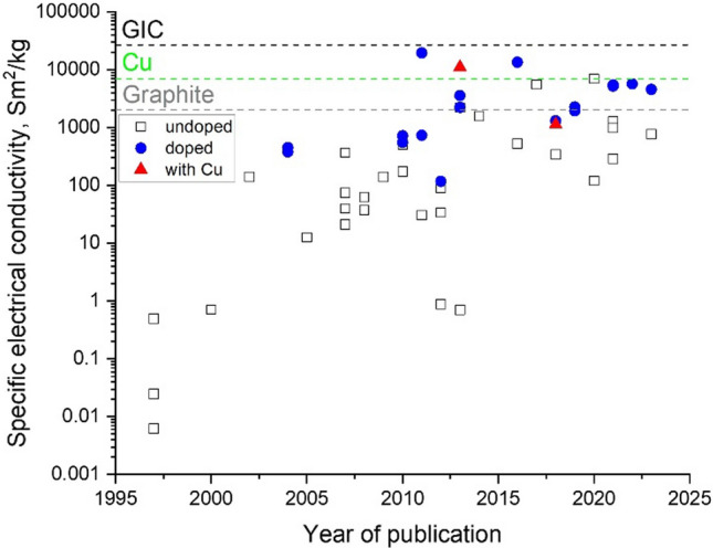
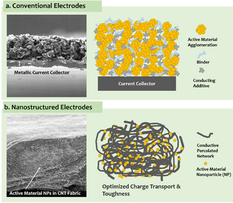
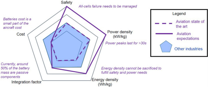
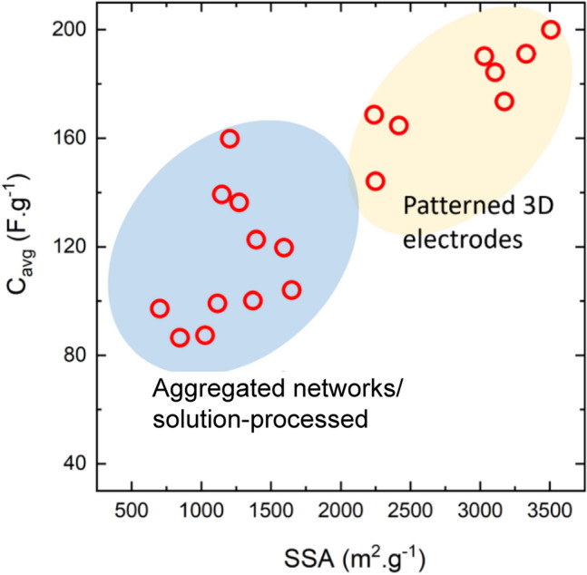
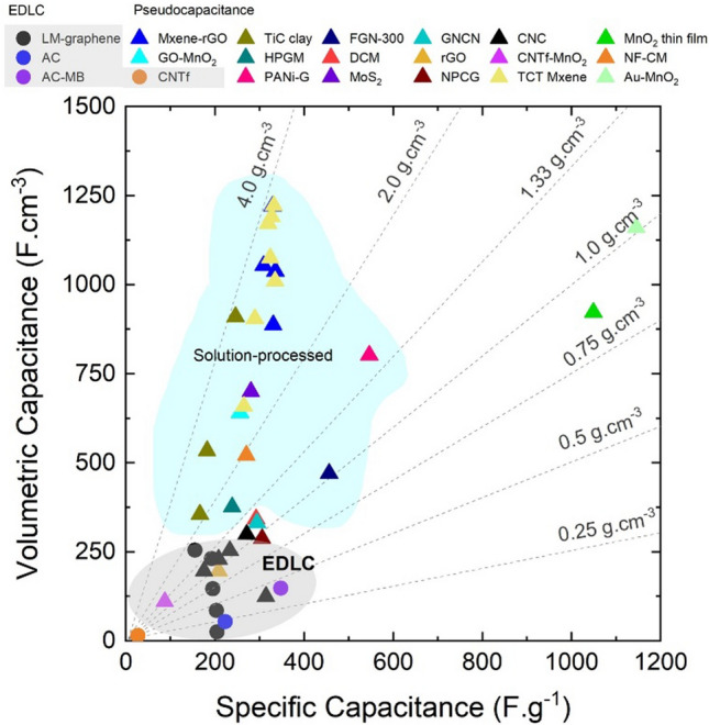
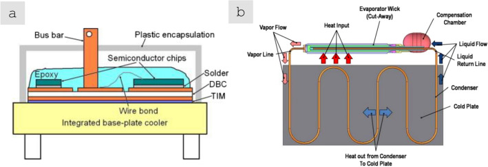
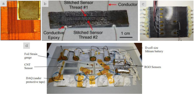
New materials for electrical conductors, energy storage, thermal management, and structural elements are required for increased electrification and non-fossil fuel use in transport. Appropriately assembled as macrostructures, nanomaterials can fill these gaps. Here, we critically review the materials science challenges to bridge the scale between the nanomaterials and the large-area components required for applications. We introduce a helpful classification based on three main macroscopic formats (fillers in a matrix, random sheets or aligned fibres) of high-aspect ratio nanoparticles, and the corresponding range of bulk properties from the commodity polymer to the high-performance fibre range. We review progress over two decades on macroscopic solids of nanomaterials (CNTs, graphene, nanowires, etc.), providing a framework to rationalise the transfer of their molecular-scale properties to the scale of engineering components and discussing strategies that overcome the envelope of current aerospace materials. Macroscopic materials in the form of organised networks of high aspect ratio nanomaterials have higher energy density than regular electrodes, superior mechanical properties to the best carbon fibres, and electrical and thermal conductivity above metals. Discussion on extended electrical properties focuses on nanocarbon-based materials (e.g., doped or metal-hybridised) as power or protective conductors and on conductive nanoinks for integrated conductors. Nanocomposite electrodes are enablers of hybrid/electric propulsion by eliminating electrical transport limitations, stabilising emerging high energy density battery electrodes, through high-power pseudocapacitive nanostructured networks, or downsizing Pt-free catalysts in flying fuel cells. Thermal management required in electrified aircraft calls for nanofluids and loop heat pipes of nanoporous conductors. Semi-industrial interlaminar reinforcement using nanomaterials addresses present structural components. Estimated improvements for mid-range aircraft include > 1 tonne weight reduction, eliminating hundreds of CO2 tonnes released per year and supporting hybrid/electric propulsion by 2035.

Keywords: Aircraft; Battery; Energy; Nanocomposite; Nanotube; Nanowire.


Conflict of interest statement

Declarations. Competing interests: Tamara Blanco reports financial support provided by Airbus Group SE.

Figures

Fig. 1
Fig. 1
ATAG way point report—Scenario 3: aspirational and aggressive technology perspective [13]. Copyright 2021 The Air Transport Action Group (ATAG)
Fig. 2
Fig. 2
Progression of electric technology for commercial transport aircraft—NASA’s Vision [17]. Copyright 2015 NASA, Work of the US Gov
Fig. 3
Fig. 3
Propulsion power evolution for aviation electrification route—Airbus vision. Copyright 2024 Airbus
Fig. 4
Fig. 4
Comparison of the size of a nanoparticle (C60 molecule) and the “small” gap between closed-packed CF filaments in a structural composite. Copyright 2024 IMDEA Materials
Fig. 5
Fig. 5
Comparison of crystalline domains in a, b CF with c the length of a CNT (a single, continuous layer of graphene) extending over centimetres [41, 42]. a, b Adapted from [41] with permission. Copyright 2005 Springer Nature. c Adapted from [42] with permission. Copyright 2018 Springer Nature
Fig. 6
Fig. 6
Main macroscopic architectures of nanomaterials relevant to aeronautical components: a Randomly dispersed fillers, typically at low volume fraction, in a polymer matrix, simple to manufacture but with low-level properties (examples: TEM micrograph of ~ 1% vol. MWCNT-composite prepared by a masterbatch dilution method [57]; inset to a commercial polymer masterbatch with Graphistrengh® MWCNTs by Arkema (Copyright 2024 Arkema). b Sheets or fabrics of high aspect ratio nanoparticles (e.g., nanotubes), which could be combined with macroscopic constituents, for example CFRP hybrids, to complement properties or enable new ones (examples: multifilament CNT fabric from the floating-catalyst CVD synthesis [58]; inset to b commercial non-woven sheet of CNTs by Tortech Nano Fibers Ltd. (Copyright 2017-2024 Tortech Nano Fibers Ltd.). c Fibres of highly aligned nanomaterials, with high volume fraction and high-performance properties (examples: magnified view of the highly-aligned CNT fibre spun from liquid crystalline solution [111]; inset to c commercial continuous CNT fibre by DexMat Inc. (Copyright 2018-2024 DexMat Inc.)). a Reproduced from [57] with permission. Copyright 2005 Taylor & Francis. b Adapted from [58] under the Creative Commons CC-BY license. c Adapted from [111] with permission. Copyright 2021 Elsevier
Fig. 7
Fig. 7
Main macroscopic architectures of nanomaterials relevant to aeronautical components: a Zeon Corporation plant in Japan (Copyright 2016 Zeon Corporation; https://sciencex.com/wire-news/225539173/worlds-first-super-growth-carbon-nanotube-mass-production-plant.html); b 1000 tonnes per year plant facilities of CNT arrays developed by Tsinghua University (China) [25]; c LG Chem’s Yeosu Plant (South Korea) (Copyright 2020 LG Chem; https://www.chemengonline.com/lg-chem-to-expand-carbon-nanotube-production-capacity/); and d new plant of Veelo Technologies (USA) (Copyright 2019 Veelo Technologies; https://www.compositesworld.com/articles/plant-tour-veelo-technologies-woodlawn-ohio-us). b Adapted from [25] with permission. Copyright 2018 John Wiley and Sons
Fig. 8
Fig. 8
Electrical conductivity of nanocomposites with randomly dispersed nanoparticles, and their macroscopic ensembles (sheets and fibres). Copyright 2024 IMDEA Materials
Fig. 9
Fig. 9
Improvements in specific electrical conductivity of continuous nanocarbon fibres achieved through structural improvements, introduction of dopants and hybridisation with metals. Copyright 2024 IMDEA Materials
Fig. 10
Fig. 10
Examples of continuous fibres of intercalated nanocarbons with high electrical conductivity. a FeCl3-intercalated bundles of CNT in a macroscopic yarn [116]. b Fibres produced from graphene intercalated with different guest compounds [114]. c XRD patterns of the pure and doped graphene fibres. a Adapted from [116] with permission. Copyright 2021 Elsevier. b, c Adapted from [114] with permission. Copyright 2016 John Wiley and Sons
Fig. 11
Fig. 11
Cu/Nanocarbon fibre hybrids. a Example of a hybrid continuous fibre of CNT/Cu with superior specific electrical conductivity and specific ampacity than pure Cu [49] and b literature data showing specific conductivity values above Cu for aligned CNTs with electrodeposited Cu [119]. a Adapted from [49] under the Creative Commons CC-BY license. b Adapted from [119] under the Creative Commons CC-BY license
Fig. 12
Fig. 12
Increasing need for conductors in emerging aircraft. a Evolution of required electrical power in civil aircraft [123] and b Historical data showing a linear increase in weight from electrical wiring and distribution/interconnection systems with installed consumer power. Copyright 2017 NASA, Work of the US Gov
Fig. 13
Fig. 13
Aircraft conductors grouped in different classes in terms of maximum peak current sustained and other dominant properties: power cables, protective conductors, and integrated conductors and data transfer. Copyright 2024 IMDEA Materials
Fig. 14
Fig. 14
Power conductor of CNT fibres. a Fabrication by dye densification of commercial sheets of CNTs. Diameter decreases from 22.5 mm to the final 6 mm diameter after densification. b Scaling law for maximum current and linear density [127]. a, b Adapted from [127] with permission. Copyright 2017 AIP Publishing
Fig. 15
Fig. 15
Schematic with LSP zoning in conventional commercial aircraft . Reproduced from  [128] under the Creative Commons BY-NC license
Fig. 16
Fig. 16
Lightning strike protection test [0]8 woven carbon fabric laminate with a Cu foil and b CNT fibre veils, performed at low energy strike conditions (100 kA) according to EUROCAE ED84 [132]. Copyright 2024 IMDEA Materials
Fig. 17
Fig. 17
a, b Images of the CFRP boxes with CNT material EMI protection, post autoclave moulding; c EMI attenuation as a function of frequency fortested EMI boxes [140]. ac Adapted from [140] under the Creative Commons CC-BY license
Fig. 18
Fig. 18
Co-axial cables from CNT fibres. a Fabrication of a coaxial cable with core and sheath of CNT fibre sheets. b Attenuation level showing improve performance when using doped CNT material [142].  a, b Adapted from [142] with permissions. Copyright 2012 American Chemical Society
Fig. 19
Fig. 19
a, b Schematic of the screen-printing method and the device printed on PET substrate [146]; c schematic of the inkjet printing the graphene-based ink on Si/SiO2 substrate with d the optical micrograph of inkjet-printed graphene stripe on HMDS-treated substrate with minimised “coffee-ring” effect [150]; examples of inkjet printed e highly-flexible graphene lines printed on Kapton film [154] and f pillars fabricated from silver nanoparticles assembled with a light emitting diode [155]; g schematic of the direct ink writing method (inset: direct writing of Ag/TPU ink through the 200 µm-nozzle, scale bar 200 µm) with examples of printed h electrodes in a 24-pad wiring scheme with electrode widths 100 µm, i microcontroller circuit fabricated by hybrid 3D printing, and j LED device showing interface of surface mount LED connected with Ag/TPU electrodes [156]; k schematic of the fused deposition modelling 3D printing process [157] with examples of l the letters “NANO” printed using a single CNT yarn-based filament showing 90°, 180° and large radius turns, and m powering the 1W bulb through the printed resin-rich specimen with continuous CNT yarn [158]. a, b Adapted from [146] with permission. Copyright 2014 American Chemical Society. c, d Adapted from [150] with permission. Copyright 2012 American Chemical Society. e Adapted from [154] with permission. Copyright 2012 American Chemical Society. f Adapted from [155] under the Creative Commons CC-BY license. gj Adapted from [156] with permissions. Copyright 2017 John Wiley and Sons. k Adapted from [157] under the Creative Commons CC-BY 4.0 license. l, m Adapted from [158] with permissions. Copyright 2016 Elsevier
Fig. 20
Fig. 20
Example of  the ice protection system (IPS) —Piccolo tube [167]. Reprinted from [167] under the Creative Commons CC-BY 4.0 license
Fig. 21
Fig. 21
a Graphene serpentine/circuit for ice protection system, b flat panel with integrated graphene serpentine by co-curing. a, b Reproduced from [173] under the Creative Commons BY-NC-SA license
Fig. 22
Fig. 22
Curved panel (HTP leading edge shape) with integrated graphene serpentine by co-curing. Reproduced from [173] under the Creative Commons BY-NC-SA license
Fig. 23
Fig. 23
Ragone plot for different energy storage systems, including ICE and a rule of mixture for a linear combination of fuel cells and supercapacitors. Some example electric/hybrid concept vehicles are superimposed. Copyright 2024 IMDEA Materials
Fig. 24
Fig. 24
Comparison of the microstructure of a a traditional battery electrode and b a nanostructured electrode with carbon network. Copyright 2024 IMDEA Materials
Fig. 25
Fig. 25
SEM images of the LIB cathodes (e.g., NMC 811) with different conducting fillers: a carbon black, b SWCNT, and c graphene layers with various mass fraction of the filler. For each case, the in-plane (IP) and out-of-plane (OOP) conductivities and their specific capacities (Q/M) vs. charge–discharge rate (R = (I/M)/(Q/M)) in several mass fractions are depicted. Due to high aspect ratio, SWCNTs form percolating networks at lower mass fractions. The threshold for electrical limitations on capacity at high rates is an OOP conductivity of ~ 1 S/m [186]. ac Adapted from [186] with permission. Copyright 2020 American Chemical Society
Fig. 26
Fig. 26
The application of lithiophilic nanocarbons as host or buffer to retain Li for batteries with high energy density. a layered rGO with nanoscale interlayer gaps as stable Li host with low dimension variation of ~ 20%, retaining a high capacity of ~ 3390 mAh/g and flat voltage. SEM micrographs of the sample after 10 cycles are compared to that of metallic Li electrode [200]. b Schematic showing crumpled graphene balls (CGB) capable to support high Li metal loading without volume fluctuation and further Li deposition on top of the sample without dendrite formation. SEM shows the Li deposited on a 40 µm thick CGB electrode [202]. c The effect of CNT as a buffer layer to store Li during plating/stripping. SEM micrographs show the comparison of the Li metal with and without the CNT buffer layer after cycling [203]. d Schematic diagram of the Li deposition and stripping process on one graphene flake along with SEM micrograph of the electrode after Li deposition at 0.5 mA/cm.2 [204]. a Adapted from [200] with permission. Copyright 2016 Springer Nature. b Adapted from [202] with permission. Copyright 2018 Elsevier. c Adapted from [203] with permission. Copyright 2016 Royal Society of Chemistry. d Adapted from [204] with permission. Copyright 2016 John Wiley and Sons
Fig. 27
Fig. 27
Nanocomposite electrodes with reduced content of materials. (i) a, b Nanocomposite of Si and 7.5% wt. (optimised) of SWCNT, without polymeric binder [185]. As it is seen from the SEM micrographs (c-h) the segregated network could be achieved at > 1% wt. of SWCNTs for microsized Si particles while such network did not form in the case of Si NPs. (ii) Olivine LiFePO4 cathode electrodes with CNT fibre-based fabrics as current collector accounting for 18% wt., compared to 58% wt. for regular Cu foil (electrode level)[223]: a the bare CNTf, b slurry-coated, c dried films and d cross-sectional SEM micrographs of the electrodes. (i) Reproduced from [185] with permission. Copyright 2019 Springer Nature. (ii) Adapted from [223] with permission. Copyright 2019 American Chemical Society
Fig. 28
Fig. 28
Estimated energy density required for different 180 pax hybrid/electrical concept aircraft, with current values for commercial and laboratory-scale LIBs. Copyright 2024 IMDEA Materials
Fig. 29
Fig. 29
Schematic representation of the importance of different performance indicators in aviation batteries [225]. Copyright 2020 Airbus
Fig. 30
Fig. 30
Example of a structural battery enabled by nanoconstituents, including aramid nanofibres (ANF). a Structure and photograph of a layered device. b Voltage profiles and c Example of a UAV with an energy-storing body [227]. ac Adapted from [227] with permission. Copyright 2019 American Chemical Society
Fig. 31
Fig. 31
a Schematic of different electrochemical energy storage mechanisms [231]: (1) electrical double-layer capacitor, (2) pseudocapacitive (surface-confined reactions), and (3) Faradaic electrodes; and examples of related nanostructured electrodes: b CNT network [232], c MnO2 decorated CNT fibres [233], and (d conformal MoS2 on CNT fibres [110]. a Reproduced from [231] with permission. Copyright 2019 John Wiley and Sons. b Adapted from [232] with permission. Copyright 2019 Elsevier. c Adapted from [233] with permission. Copyright 2017 Elsevier. d Adapted from [110] with permission. Copyright 2021 American Chemical Society
Fig. 32
Fig. 32
Dependence of specific capacity on specific surface area of nanocarbons in EDLCs [239]. Adapted from [239] with permission. Copyright 2014 Springer Nature
Fig. 33
Fig. 33
Electrochemical performance of some selected pseudocapacitive material (with a mass loading > 0.5 mg/cm2) in aqueous (blue) and nonaqueous (green) media in comparison with benchmark EDLC (~ 20 mAh/g in ~ 1 s). Colour gradient intensity represents the required charging time [238]. Reproduced from [238] with permission. Copyright 2019 Springer Nature
Fig. 34
Fig. 34
Comparison of the specific and volumetric capacitance of a large pool of materials (EDLC, circles and pseudo-capacitance, triangles) reported in literature. The dashed lines display the apparent density of the electrodes. The grey ellipsoidal shadow shows the aggregation of pure EDLC electrodes. The data have been collected from the ref. [, , –267]. Copyright 2024 IMDEA Materials
Fig. 35
Fig. 35
Galvanostatic discharge profiles for various pseudocapacitive materials in comparison with a battery electrode of LiCoO2 (bulk LCO) [238]. Reproduced from [238] with permission. Copyright 2019 Springer Nature
Fig. 36
Fig. 36
Multifunctional properties of carbon materials for structural supercapacitors. Copyright 2024 IMDEA Materials
Fig. 37
Fig. 37
Structural supercapacitor composite architectures: a laminated structure with a nanoporous monolithic carbon phase as active material and stiff matrix [278]; b,c energy-storing interleaves with patterns for lamina interconnection through structural resin plugs [279, 280]. a Reprinted from [278] with permission. Copyright 2013 Elsevier. b Adapted from [279] under the Creative Commons CC-BY license. c Reprinted from [280] with permission. Copyright 2022 Elsevier
Fig. 38
Fig. 38
Schematic illustration of a fuel cell [292]. Reproduced from [292] with permission. Copyright 2006 European Organisation for the Safety of Air Navigation EUROCONTROL
Fig. 39
Fig. 39
Schematic representation of various fuel cell types, showing their operation temperature range, common electrolytes as well as the general trend for their efficiency, complexity, fabrication, and material cost. SOFC: Solid Oxide Fuel Cell; MCFC: Molten-Carbonate Fuel Cell; PAFC: Phosphoric Acid Fuel Cell; PEMFC: Proton-Exchange Membrane Fuel Cell; AFC: Alkaline Fuel Cell; YSZ: Y2O3-ZrO2 electrolyte; PA: Phosphoric Acid; PFSA: Perfluorosulfonic Acid [294]. Reprinted from [294] under the Creative Commons CC-BY license
Fig. 40
Fig. 40
Breakdown of fuel cell stack costs [292]. Adapted from [292] with permission. Copyright 2006 European Organisation for the Safety of Air Navigation EUROCONTROL
Fig. 41
Fig. 41
Historical evolution of endurance of FC-powered UAVs. Reproduced from [311] with permission. Copyright 2017 Elsevier
Fig. 42
Fig. 42
Schematic presentation of application and power range of the main FCs as a function of their operational temperature [294]. Reprinted from [294] under the Creative Commons CC-BY license
Fig. 43
Fig. 43
Mechanical reinforcement with high-aspect ratio carbon nanomaterials. a Specific tensile modulus of the main embodiments of CNTs and graphene, showing the increase in load transfer with improved packing of elements. b,c Different routes to use nanomaterials in aeronautical composites: as fillers for matrix reinforcement, as sheets or aligned arrays [326] for interlaminar reinforcement and as reinforcing fibres [327]. a Copyright 2024 IMDEA Materials. b Adapted from [326] with permission. Copyright 2008 Elsevier. c Reproduced from [327] with permission. Copyright 2009 Elsevier
Fig. 44
Fig. 44
Strategies for interlaminar reinforcement with nanocarbons. a Prepegs with arrays of vertically-aligned short CNTs, termed ‘nanostitching’ [332]. b An example of a 3-dimensional CNT-reinforced composite: a ‘fuzzy-fibre’ composite with in situ-grown radially-aligned CNTs on the woven cloth [329]. a Reproduced from [332] with permission. Copyright 2016 Elsevier. b Reproduced from [329] with permission. Copyright 2008 Elsevier
Fig. 45
Fig. 45
Properties of fibres of nanocarbons. a Analogy to polymers used for high-performance fibres: 1—polyethylene; 2—nylon 6; 3—meta-aramid (Nomex); 4—para-aramid (Kevlar); 5—LC aromatic polyester (Vectran); 6—PBO (Zylon); 7—a single-walled CNT as the “ultimate” polymer. b,c Tensile properties of CNT and graphene fibres compared to other materials, including high-performance CF (T300, T1100GC, M35JB, M60JB, AS4, AS7, IM10, HM63), polymer fibres (Techora, Vectran-HT, Vectran-UM, Kevlar 29, Kevlar 49, Dyneema SK75, Zylon), glass fibres (S-glass, R-glass), and metals (Ti–6Al–4V, SS316, Al6061). Copyright 2024 IMDEA Materials
Fig. 46
Fig. 46
a CNT prepreg spools, b,c CNT yarn laminates and a SEM cross-section showing densely-packed CNT yarns; d specific tensile modulus and strength unidirectional CNT yarn laminates compared to the state-of-the-art high-modulus and high-strength CF composites. a Adapted from [352] with permission. Copyright 2024 Elsevier. b-d Adapted from [141] with permission. Copyright 2024 Elsevier
Fig. 47
Fig. 47
Material breakdown in last generation A350 aircraft. Copyright 2024 Airbus
Fig. 48
Fig. 48
a CNT yarn-composite overwrapped pressure vessel for aerospace vehicles [358]. Adapted from [358] with permission. Copyright 2016 Elsevier
Fig. 49
Fig. 49
Thermal conductivity of macroscopic nanomaterials. a Thermal conductivity for different nanobuilding blocks organised as randomly oriented fillers, sheets or aligned fibres. b Progression on fibres of aligned CNTs and graphene at the high end of specific thermal conductivity. Copyright 2024 IMDEA Materials
Fig. 50
Fig. 50
Examples of thermal management systems relevant for aircraft. a Thermal interface material and the integrated base-plate cooler in a typical power electronics package [367]. b Loop Heat Pipe. a Reprinted from [367] with permission. Copyright 2013 Elsevier. b Reprinted from [368] with permission. Copyright 2009 ASME
Fig. 51
Fig. 51
a Schematic of the two-phase flow loop in heat pipes, b Porous copper wick with a nano-layer of GO [375], c nickel wick coupon coated with graphene slurries [376], d graphene-coated loop heat tested in a vacuum chamber[373]. a,b Adapted from [375] with permission. Copyright 2018 Elsevier. c Adapted from [376] with permission. Copyright 2016 Elsevier. d Reprinted from [373] under the Texas Tech University Repository Submission License
Fig. 52
Fig. 52
Approximate carbon footprint of selected aviation materials. Sources: Cu, Ti, Al, CF [384], CB [385, 386]. Copyright 2024 IMDEA Materials
Fig. 53
Fig. 53
a Comparison of oven and out-of-oven manufacturing process for laminate curing [412]; b HDPE/GNP heating film for out-of-oven curing of glass fibre reinforced thermoset laminate [411]; c manufacturing of laser-induced graphene heating elements [174]. a Adapted from [412] with permission. Copyright 2018 Elsevier. b Adapted from [411] with permission. Copyright 2020 Elsevier. c Reprinted from [174] with permission. Copyright 2022 Elsevier
Fig. 54
Fig. 54
a, b The out-of-oven curing of CFRP composites using a dielectric barrier discharge applicator, c complex geometries of CF. a-c Adapted from [416] with permission. Copyright 2024 Elsevier
Fig. 55
Fig. 55
Examples of the piezoresistive strain sensors based on CNT yarns: a individually positioned in micro-channels in a polyimide film [423], b stitched to GF layup [424], c fully integrated in a CFRP panel as a sensor array tested for strain sensing and impact damage detection, d directly printed on the airframe part and subjected to real flight testing [425]. a Adapted from [423] under the Creative Commons CC-BY 4.0 license. b Adapted from [424] with permission. Copyright 2010 Elsevier. c Copyright 2024 IMDEA Materials. d Adapted from [425] with permission. Copyright 2019 AIP Publishing
Fig. 56
Fig. 56
Map of properties of bulk materials of high-aspect ratio nanoparticles in different architectures. Increasing nanoparticle volume fraction towards dense solids produces increases in bulk properties from the level of polymers to above metals. Examples of the most promising applications in aircraft are listed. Copyright 2024 IMDEA Materials

References

    1. Wu K, Niu Y, Zhang Y, Yong Z, Li Q. Continuous growth of carbon nanotube films: From controllable synthesis to real applications. Compos Part A Appl Sci Manuf. 2021;144: 106359. 10.1016/j.compositesa.2021.106359.
    1. Bulmer JS, Kaniyoor A, Elliott JA. A meta-analysis of conductive and strong carbon nanotube materials. Adv Mater. 2021;33:2008432. 10.1002/adma.202008432. - PMC - PubMed
    1. Garrow L, Lurkin V. How COVID-19 is impacting and reshaping the airline industry. J Revenue Pricing Manag. 2021. 10.1057/s41272-020-00271-1.
    1. OECD Policy Responses to Coronavirus, COVID-19 and the aviation industry: impact and policy responses, 15 Oct. (2020). https://www.oecd.org/coronavirus/policy-responses/covid-19-and-the-aviat....
    1. OAG Aviation Worldwide Limited, COVID-19 AIR TRAVEL RECOVERY, (2023). https://www.oag.com/coronavirus-airline-schedules-data.

LinkOut - more resources