. 2024 Dec;40(6):3979-4005.
doi: 10.1007/s00366-024-02023-w. Epub 2024 Aug 1.

Image-to-mesh conversion method for multi-tissue medical image computing simulations

Affiliations

Image-to-mesh conversion method for multi-tissue medical image computing simulations

Fotis Drakopoulos et al. Eng Comput. 2024 Dec.

Abstract

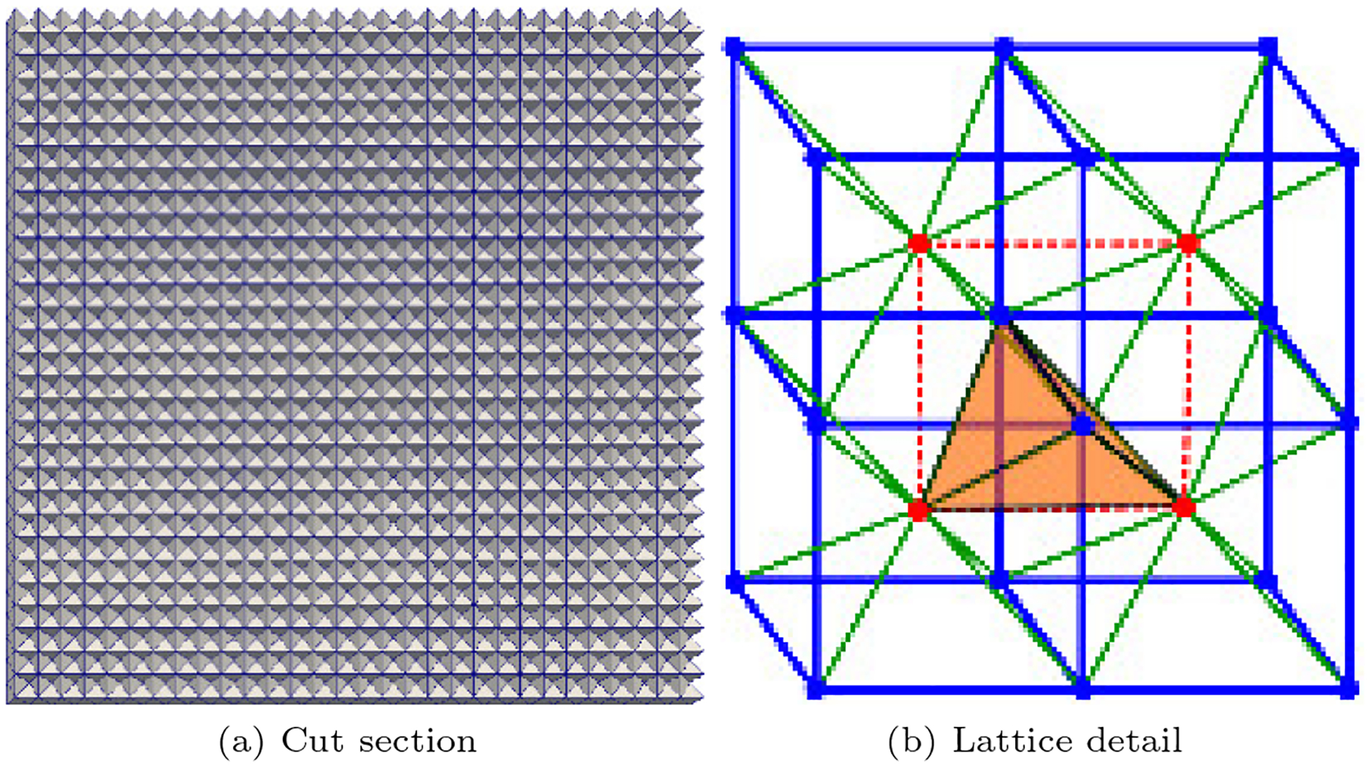
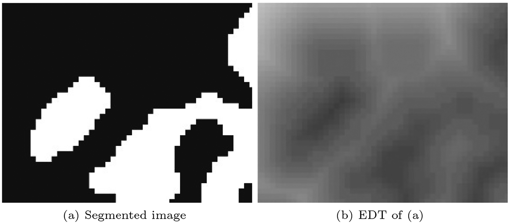
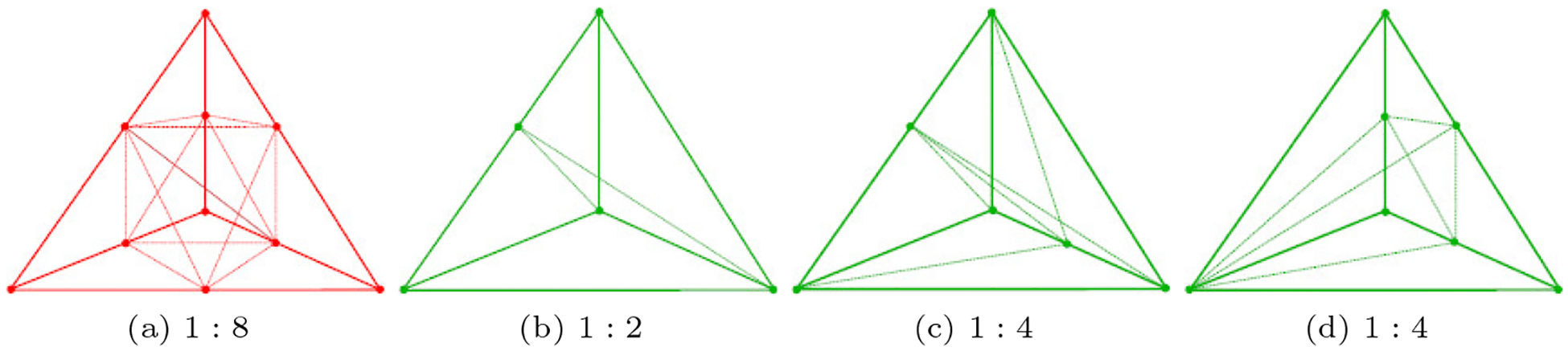
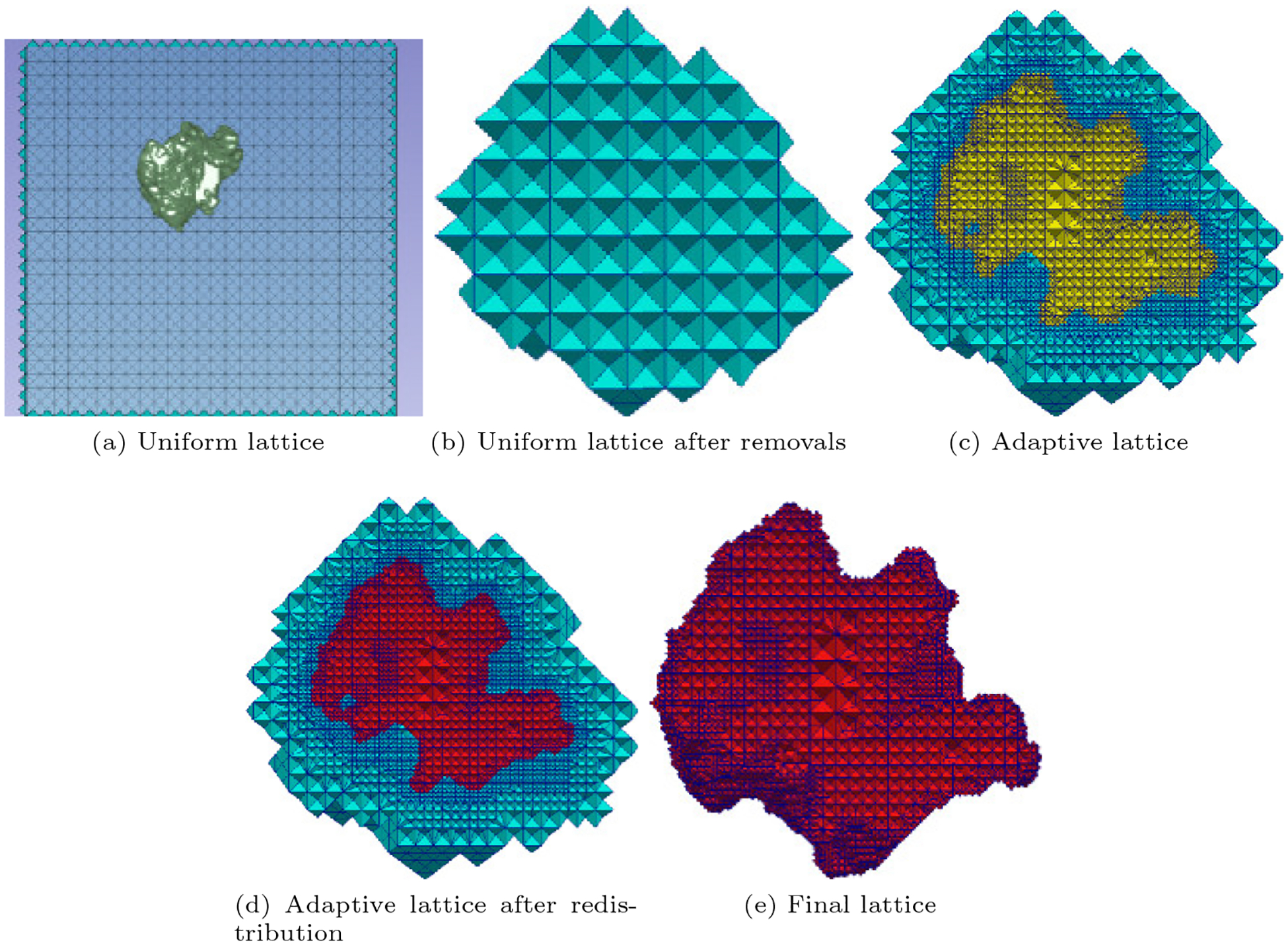
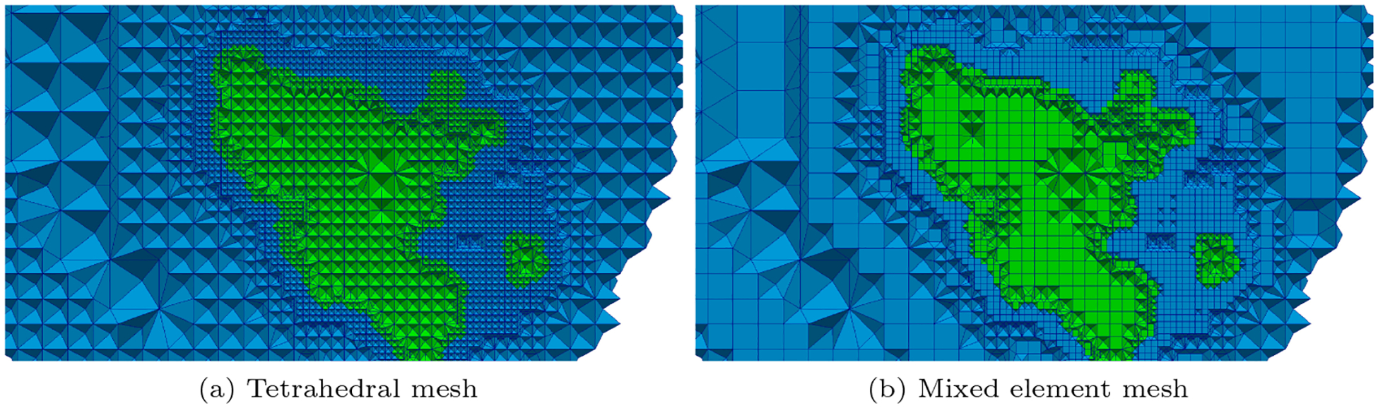
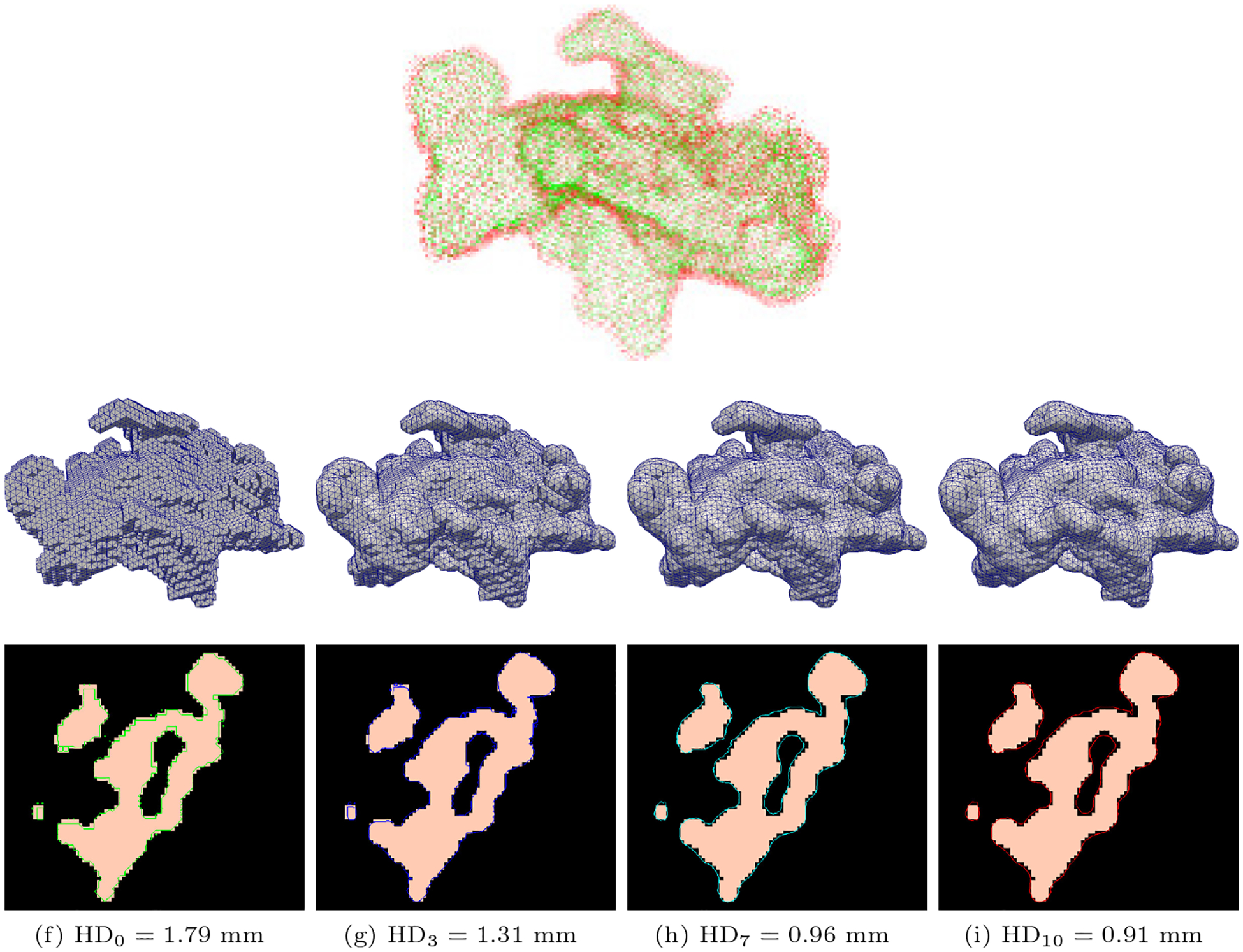
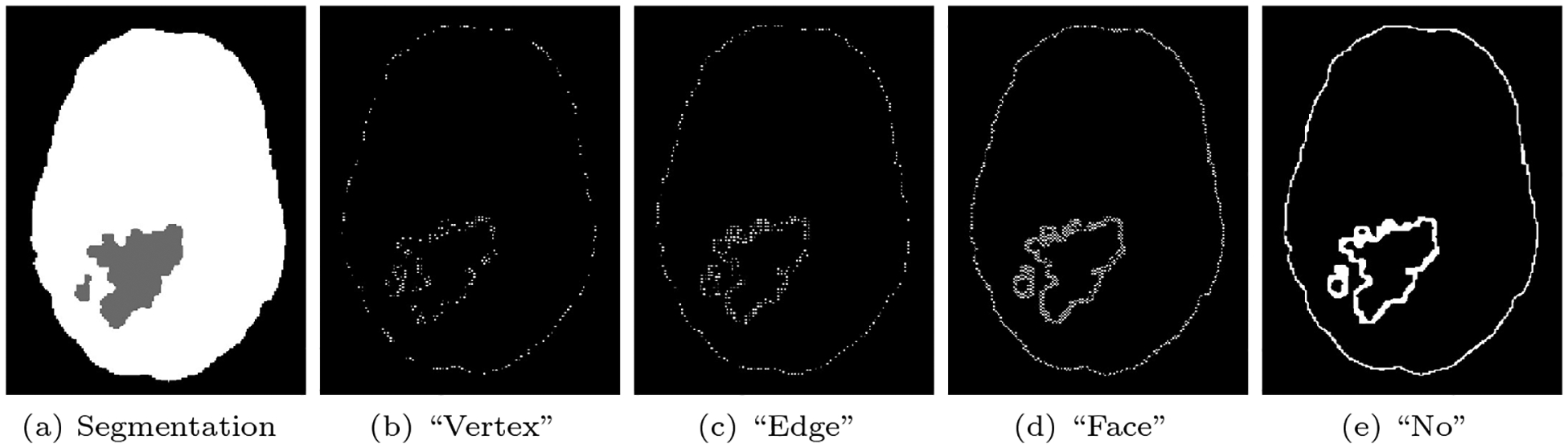
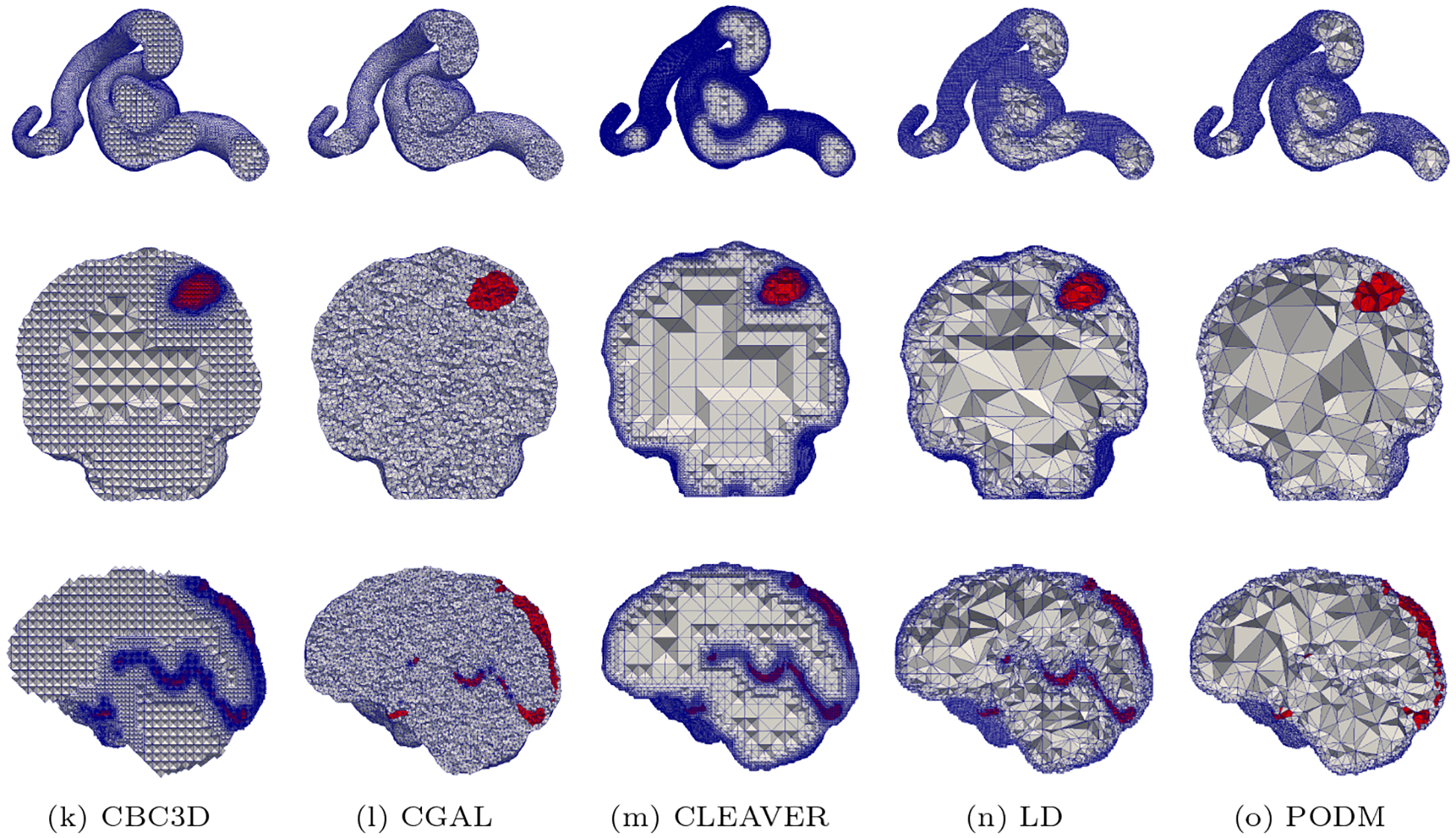
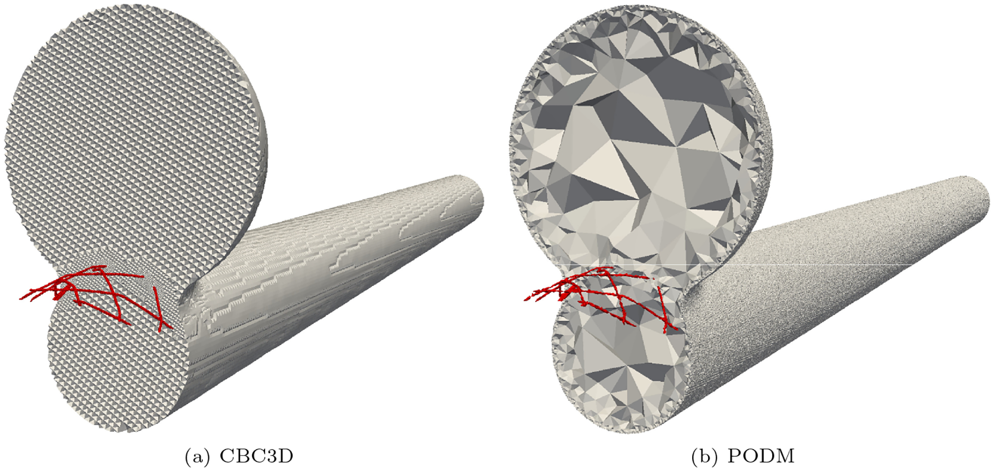
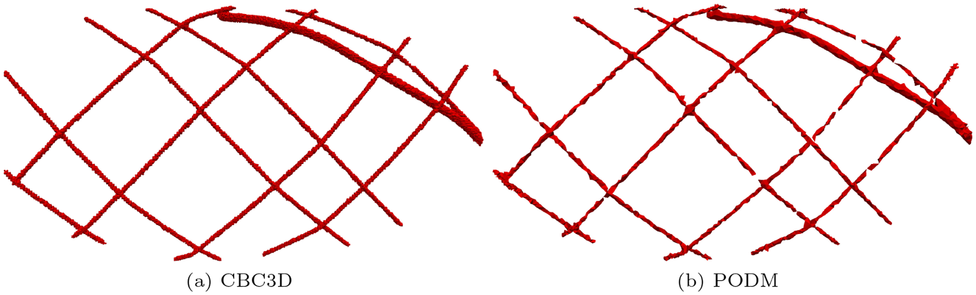
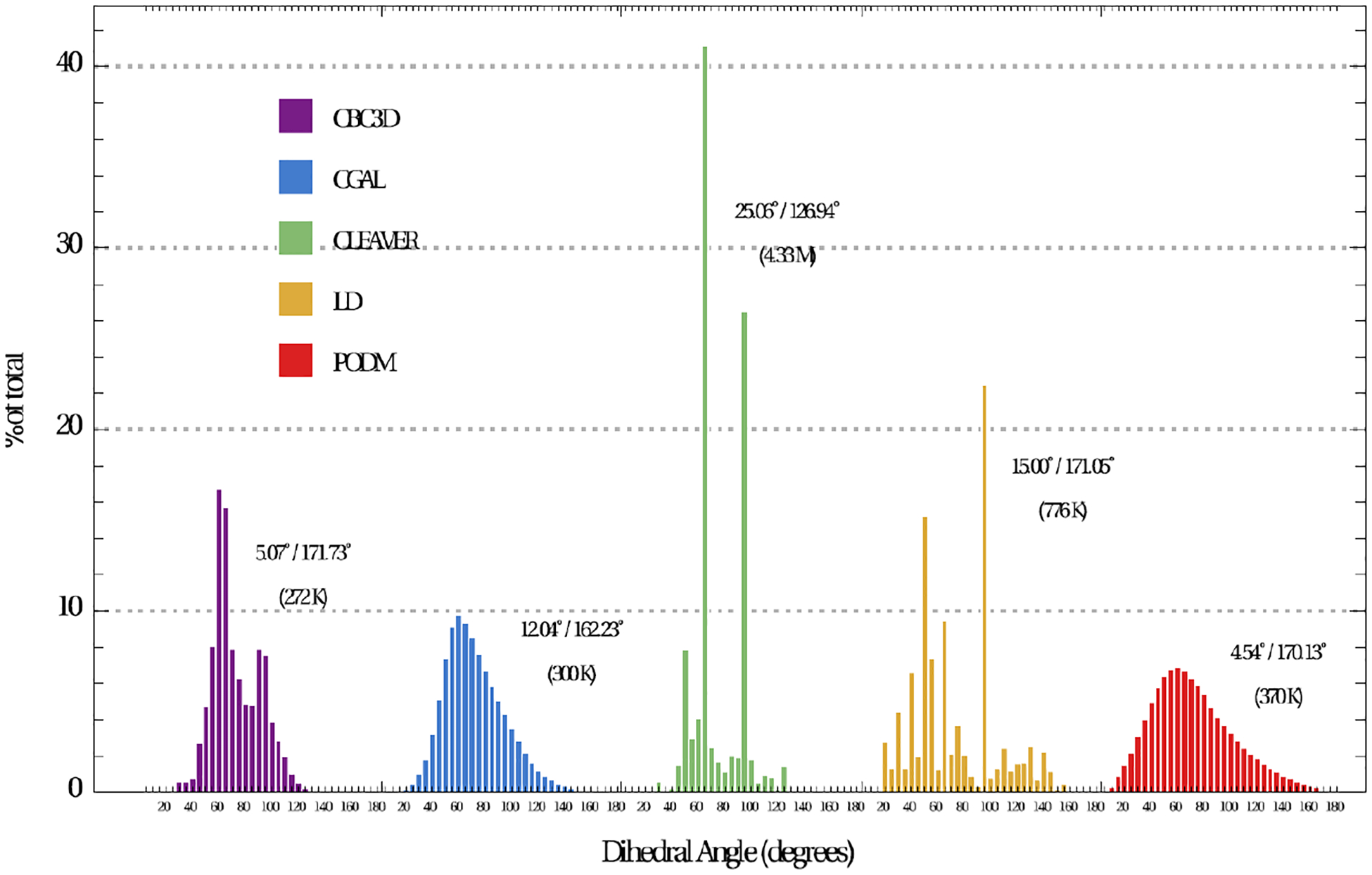
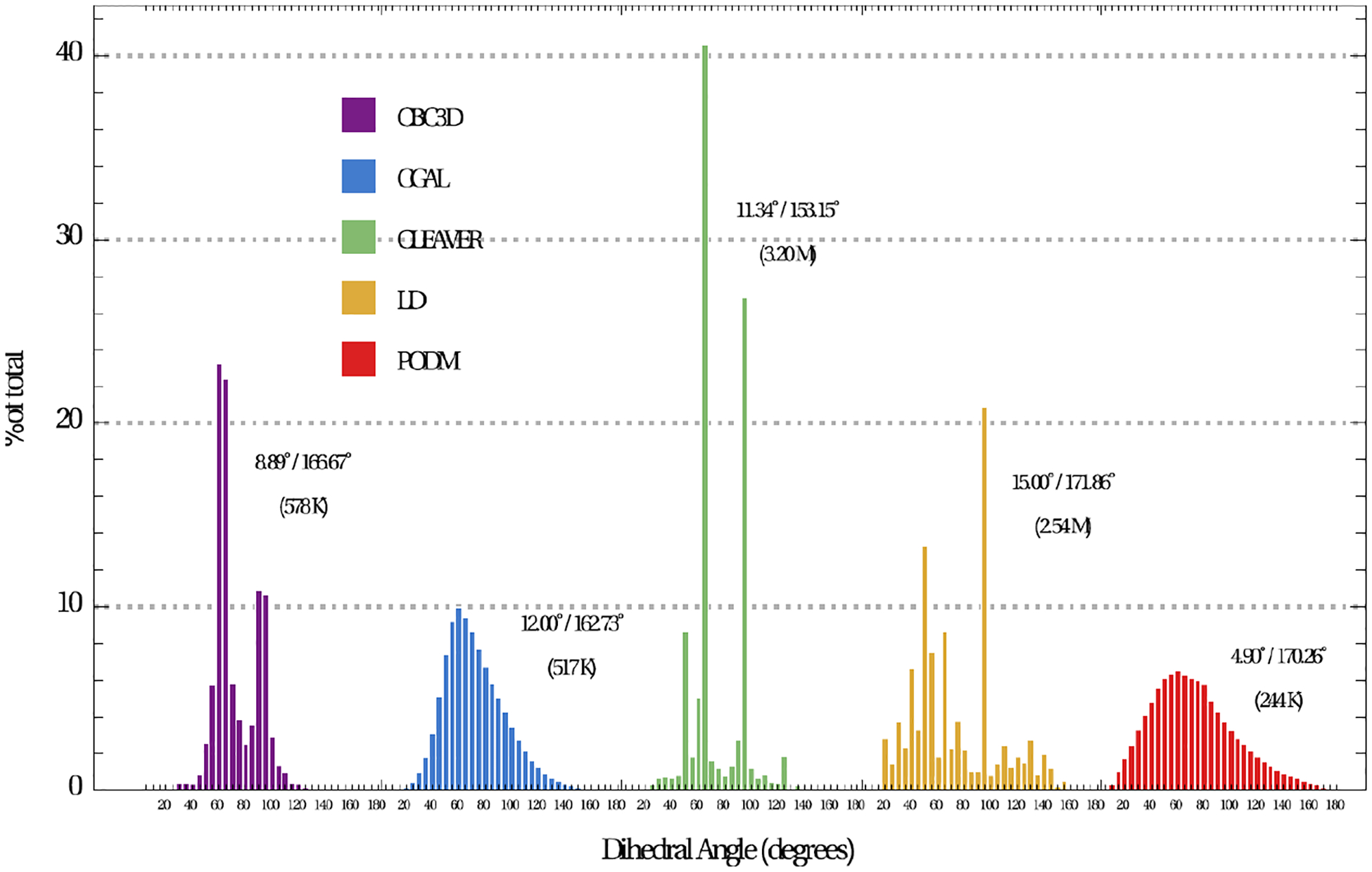
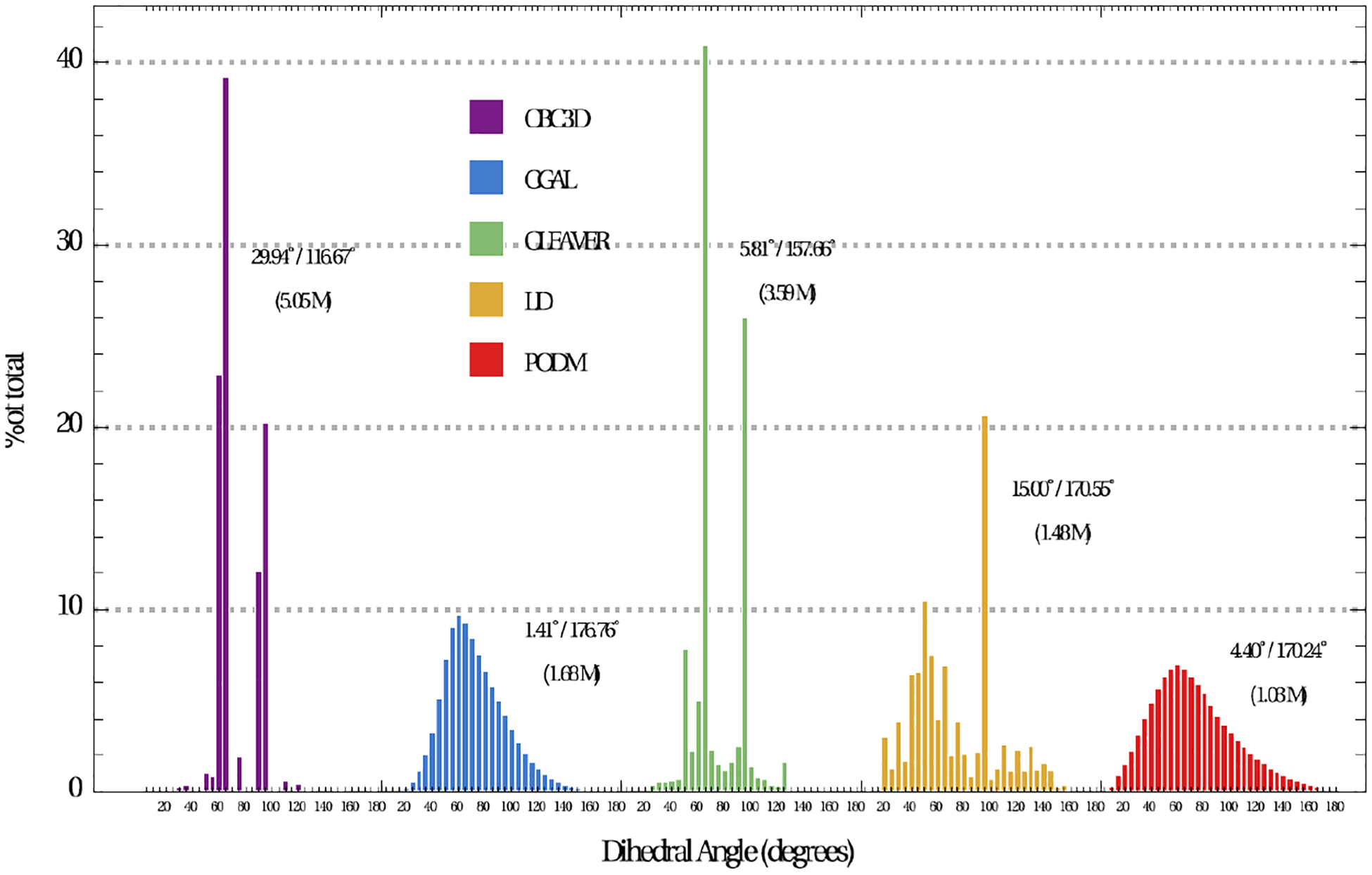
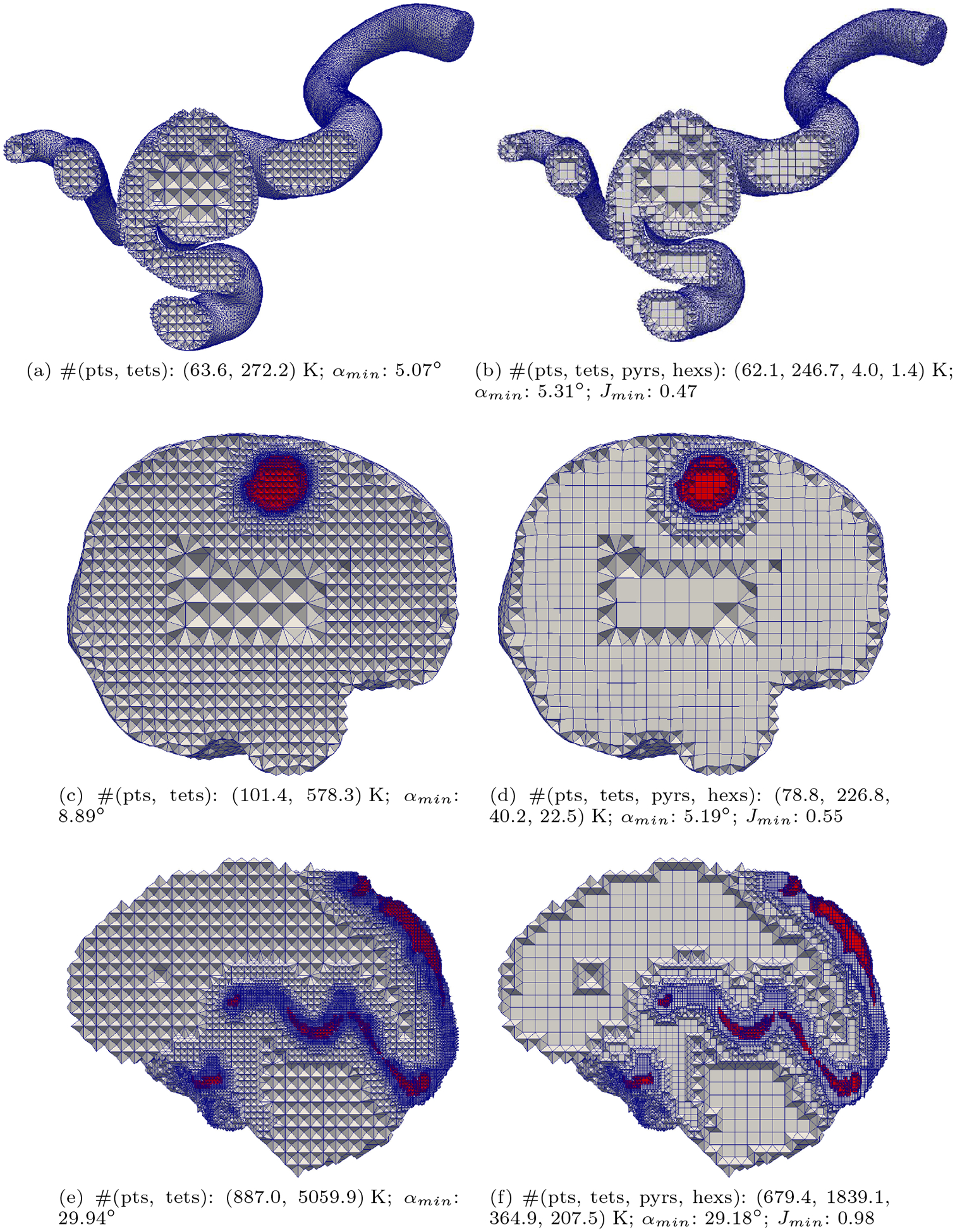
Converting a three-dimensional medical image into a 3D mesh that satisfies both the quality and fidelity constraints of predictive simulations and image-guided surgical procedures remains a critical problem. Presented is an image-to-mesh conversion method called CBC3D. It first discretizes a segmented image by generating an adaptive Body-Centered Cubic (BCC) mesh of high-quality elements. Next, the tetrahedral mesh is converted into a mixed-element mesh of tetrahedra, pentahedra, and hexahedra to decrease element count while maintaining quality. Finally, the mesh surfaces are deformed to their corresponding physical image boundaries, improving the mesh's fidelity. The deformation scheme builds upon the ITK open-source library and is based on the concept of energy minimization, relying on a multi-material point-based registration. It uses non-connectivity patterns to implicitly control the number of extracted feature points needed for the registration and, thus, adjusts the trade-off between the achieved mesh fidelity and the deformation speed. We compare CBC3D with four widely used and state-of-the-art homegrown image-to-mesh conversion methods from industry and academia. Results indicate that the CBC3D meshes (i) achieve high fidelity, (ii) keep the element count reasonably low, and (iii) exhibit good element quality.

Keywords: Image-to-mesh conversion; Medical imaging; Mesh generation; Segmentation.


Figures

Fig. 1
Fig. 1
Brain MRI slice with AVM after skull stripping [5] (a) and after segmentation (b). (c) depicts a volume rendering of the segmented AVM. The segmented image has a spacing of 0.7 × 0.7 × 1.6 mm3 and a size of 320 × 320 × 100 voxels3.
Fig. 2
Fig. 2
Raw micro-CT slice for pipeline stent model [7] (a) before (b) and after segmentation with the device wires cropped (c). (d) depicts a volume rendering of the segmented stent. The segmented image has a spacing of 0.012 × 0.012 × 0.024 mm3 and a size of 1001 × 1001 × 4421 voxels3.
Fig. 3
Fig. 3
Brain Arteriovenous Malformation (AVM) segmentation, before and after down-sampling. The red circles indicate the problematic regions after down-sampling (i.e., disconnected voxels or non-manifold voxel connectivity).
Fig. 4
Fig. 4
Candidate isolated voxels for relabeling (a)-(b) and 26-neighborhood region (c).
Fig. 5
Fig. 5
Relabeling an AVM segmented image with disconnected vessels. Before processing, the image contains one material (yellow) with five disconnected regions (a). After processing, the image contains three materials (red, cyan, and brown), each of which is a single region (b). Two small disconnected regions are relabeled to a background value.
Fig. 6
Fig. 6
Templates to eliminate a vertex-to-vertex connectivity (a) or an edge-to edge connectivity (h) in a segmented labeled image. In the case of a vertex-to-vertex connectivity, one of the six templates is randomly selected to relabel two voxels within a cluster of eight voxels (b)-(g). In the case of an edge-to-edge connectivity, one of the two templates is randomly selected to relabel a single voxel within a cluster of four voxels (i)-(j). The arrows illustrate the path of the transformation via face connected voxels after relabeling.
Fig. 7
Fig. 7
AVM anisotropic segmented image (0.7 × 0.7 × 1.6 mm3) before (a) and after (b) relabeling to eliminate the non-manifold voxel connectivity. The voxels which are connected via an edge or a vertex are depicted with red color.
Fig. 8
Fig. 8
Uniform Body-Centered Cubic (BCC) lattice. The green edges lace the two lattices together. Each vertex is surrounded by 14 edges and 24 tetrahedra.
Fig. 9
Fig. 9
Euclidean Distance Transform (EDT) computed from a labeled image. The EDT calculates the minimum distance of a voxel in the image from its closest material boundary. Voxels inside a material have a positive distance value, voxels outside a material have a negative distance value and voxels on the boundary have a zero distance value.
Fig. 10
Fig. 10
Red-Green templates for lattice subdivision. 8, 2, and 4 is the number of tetrahedra after subdivision.
Fig. 11
Fig. 11
Pipeline of the BCC lattice construction and adaptive refinement.
Fig. 12
Fig. 12
Adaptive BCC lattice before (a) and after (b) it is converted into a mixed element mesh.
Fig. 13
Fig. 13
Nidus mesh during deformation with 10 iterations. The figure on the top depicts the extracted source (green) and target (red) points used for deformation. Each column depicts the deformed mesh and an intersection between the mesh surface and the image plane at iterations i = 0, 3, 7, 10 (from left to right). HDi denotes the mesh fidelity in terms of a Hausdorff Distance metric, at iteration i. The smaller the HD value, the higher the fidelity. As the number of iterations advances, the mesh exhibits a smoother surface.
Fig. 14
Fig. 14
Extracted target points from a brain-nidus segmented image using the available connectivity patterns. Each pattern results in a different number of points. The number of points for “Vertex,” “Edge,” “Face,” and “No” patterns is 21510, 26387, 47306, and 91906, respectively. For simplicity, the points in one volumetric slice are depicted.
Fig. 15
Fig. 15
Cuts of the generated tetrahedral meshes. The top, middle, and bottom row correspond to cases 1, 2, and 3, respectively. Each column depicts meshes that are generated with a single method. Identical cut section planes are used for all the meshes in a single case. The growth from small to large elements varies among the methods. The quality of these meshes is evaluated using a min/max dihedral angle metric and an element angle distribution in 5-deg increments.
Fig. 16
Fig. 16
Cuts of the generated tetrahedral meshes of the Lumen-LVIS Stent.
Fig. 17
Fig. 17
Extracted mesh of the LVIS stent.
Fig. 18
Fig. 18
Element angle distribution (in 5-deg increments) of Cavernous Aneurysm meshes. The min/max dihedral angles and the element count are reported for each method.
Fig. 19
Fig. 19
Element angle distribution (in 5-deg increments) of Brain-Tumor meshes. The min/max dihedral angles and the element count are reported for each method.
Fig. 20
Fig. 20
Element angle distribution (in 5-deg increments) of Brain-AVM meshes. The min/max dihedral angles and the element count are reported for each method.
Fig. 21
Fig. 21
Element angle distribution (in 5-deg increments) of Lumen-LVIS stent meshes. The min/max dihedral angles and the element count are reported for each method.
Fig. 22
Fig. 22
Qualitative evaluation on the fidelity of AVM mesh. Figures (b)– (f) depict the AVM mesh (red) superimposed on the AVM segmentation (blue). The closer the mesh surface is to the boundary of the segmented material, the higher the fidelity.
Fig. 23
Fig. 23
Plots of the results in Tables 6 – 7. (b) does not include case 4 (3932.98, and 750.02 seconds for CBC3D and PODM, respectively).
Fig. 24
Fig. 24
Comparison between the surface meshes of case 1 (Cavernous Aneurysm). Each column corresponds to a single method. The bottom row depicts a closer view of the surface. Among the methods, only CBC3D approximates the voxelized segmentation with a smooth surface that reflects a certain degree of visual reality.
Fig. 25
Fig. 25
Comparison between adaptive terahedral meshes and their corresponding mixed meshes all generated with CBC3D. The top, middle, and bottom row correspond to cases 1, 2, and 3, respectively. αmin ∈ [0, 180]: minimum dihedral angle (for tetrahedra); Jmin ∈ [0, 1]: minimum scaled Jacobian (for pyramids and hexahedra).
Fig. 26
Fig. 26
Comparison between adaptive terahedral mesh and its corresponding mixed mesh for case 4 (Lumen-LVIS Stent). The meshes were generated with CBC3D. αmin ∈ [0, 180]: minimum dihedral angle (for tetrahedra); Jmin ∈ [0, 1]: minimum scaled Jacobian (for pyramids and hexahedra).

Similar articles

References

    1. Archip N, Fedorov A, Lloyd B, Chrisochoides N, Golby A, Black PM, Warfield SK: Integration of patient specific modeling and advanced image processing techniques for image-guided neurosurgery. In: Cleary KR, Galloway J Robert L (eds.) Medical Imaging 2006: Visualization, Image-Guided Procedures, and Display. Society of Photo-Optical Instrumentation Engineers (SPIE) Conference Series, vol. 6141, pp. 422–429 (2006). 10.1117/12.653930 - DOI
    1. Talos I, Archip N: Volumetric non-rigid registration for MRI-guided brain tumor surgery. Technical report, Surgical Planning Laboratory, Department of Radiology, Brigham and Women’s Hospital, Harvard Medical School; (2007)
    1. Archip N, Clatz O, Whalen S, Kacher D, Fedorov A, Kot A, Chrisochoides N, Jolesz F, Golby A, Black PM, Warfield SK: Non-rigid alignment of pre-operative MRI, fMRI, and DT-MRI with intra-operative MRI for enhanced visualization and navigation in image-guided neurosurgery. NeuroImage 35(2), 609–624 (2007) 10.1016/j.neuroimage.2006.11.060 - DOI - PMC - PubMed
    1. Drakopoulos F, Liu Y, Foteinos P, Chrisochoides NP: Towards a real time multi-tissue adaptive physics based non-rigid registration framework for brain tumor resection. Frontiers in Neuroinformatics 8(11) (2014) 10.3389/fninf.2014.00011 - DOI - PMC - PubMed
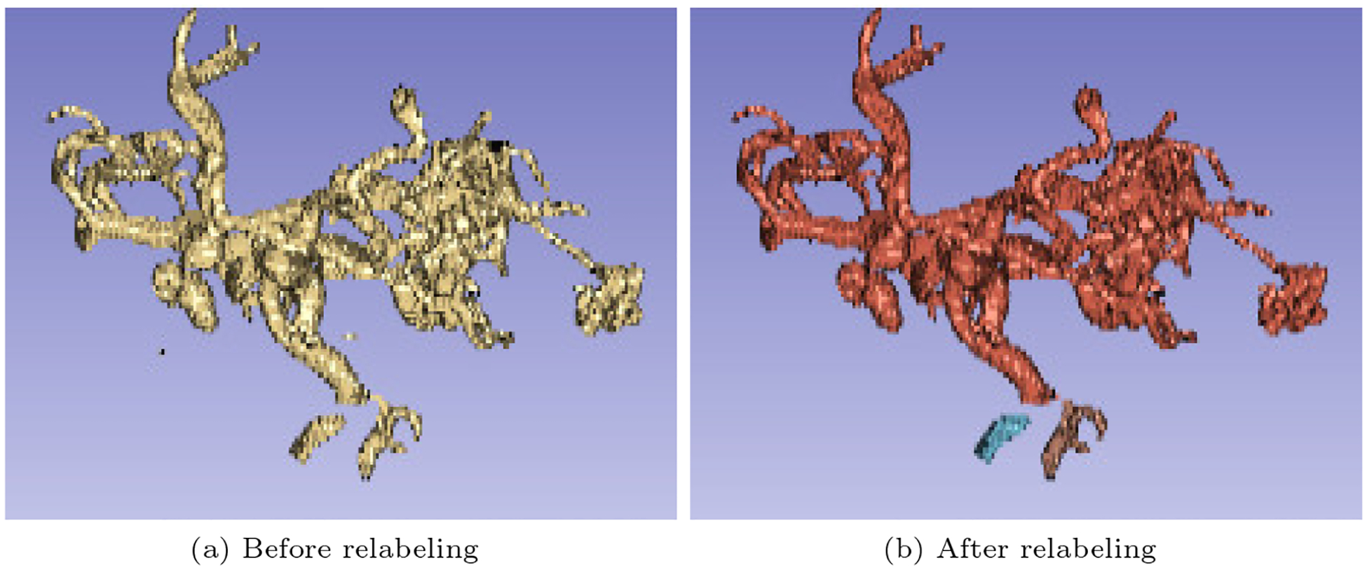
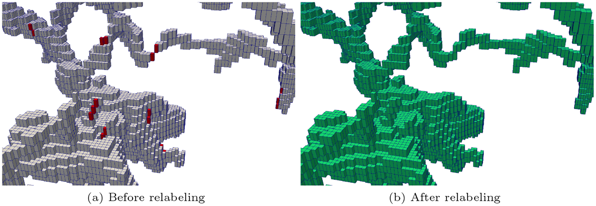
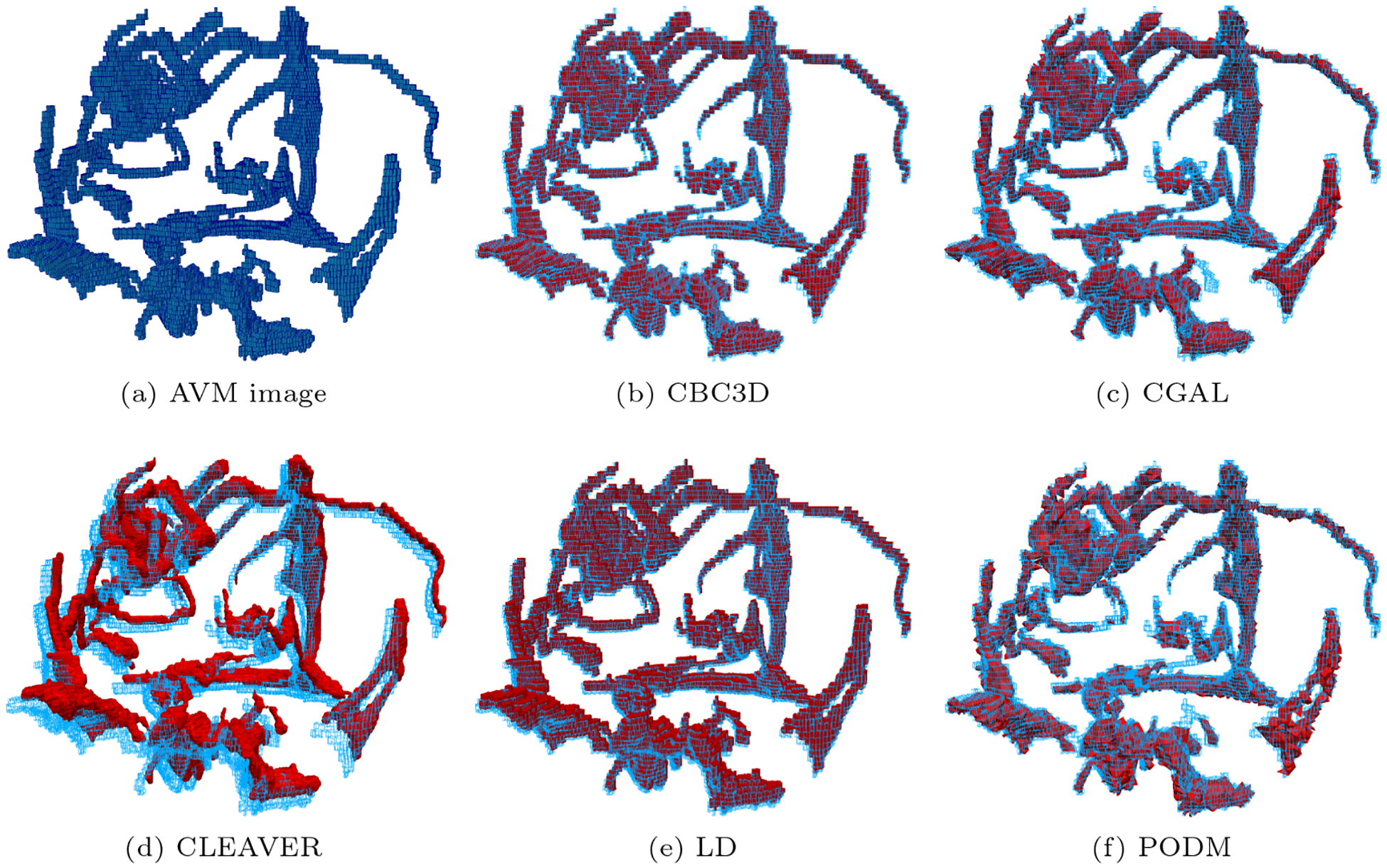
    1. Drakopoulos F, Ortiz R, Enquobahrie A, Sasaki-Adams D, Chrisochoides N: Tetrahedral image-to-mesh conversion software for anatomic modeling of arteriovenous malformations. Procedia Engineering 124, 278–290 (2015) 10.1016/j.proeng.2015.10.139. 24th International Meshing Roundtable - DOI

LinkOut - more resources