Review
. 2024 May 31;7(24):11256-11268.
doi: 10.1021/acsaem.4c00702. eCollection 2024 Dec 23.

Unlocking Micro-Origami Energy Storage

Affiliations
Review

Unlocking Micro-Origami Energy Storage

Wenlan Zhang et al. ACS Appl Energy Mater. .

Abstract

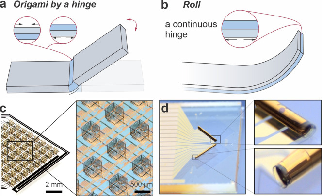
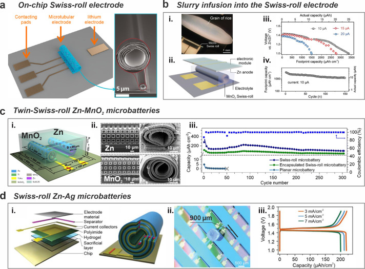
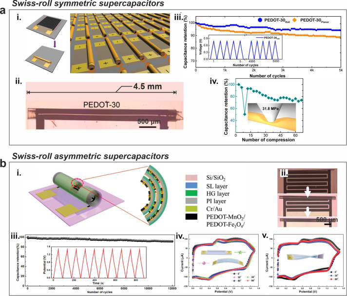
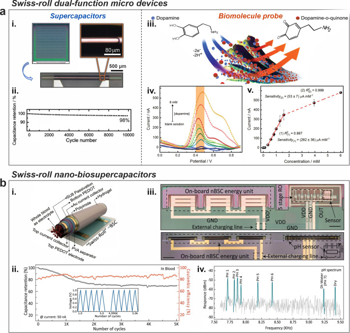
Transforming thin films into high-order stacks has proven effective for robust energy storage in macroscopic configurations like cylindrical, prismatic, and pouch cells. However, the lack of tools at the submillimeter scales has hindered the creation of similar high-order stacks for micro- and nanoscale energy storage devices, a critical step toward autonomous intelligent microsystems. This Spotlight on Applications article presents recent advancements in micro-origami technology, focusing on shaping nano/micrometer-thick films into three-dimensional architectures to achieve folded or rolled structures for microscale energy storage devices. Micro-Swiss-rolls, created through a roll-up process actuated by inherent strain in multiple layer stacks, have been employed to develop on-chip microbatteries and microsupercapacitors with superior performance compared to their planar counterparts. The technology allows additional functionalities to be integrated into the same device using multifunctional materials. Despite significant progress, the key challenge for micro-origami technology in creating microscale energy storage devices lies in diversifying shape-morphing mechanisms to expand material choices, improve process reliability, and enhance reproducibility. Additionally, developing a universal microscale energy storage device that can cater to various tiny devices is intricate. Therefore, considering the integration of energy storage into final applications during the development phase is crucial. Micro-origami energy storage systems are poised to significantly impact the future of autonomous tiny devices, such as smart dust and microrobots.


Conflict of interest statement

The authors declare no competing financial interest.

Figures

Figure 1
Figure 1
Folding and rolling. Schematics of (a) folding and (b) rolling. (c) An array of a cubic magnetic device created by the folding mechanism. Reproduced from ref (10). Available under a CC-BY 4.0 license. Copyright 2022 by the authors. (d) A Swiss-roll magnetic sensor created by the rolling mechanism. Reproduced from ref (11). Available under a CC-BY 4.0 license. Copyright 2019 by the authors.
Figure 2
Figure 2
Swiss-roll microbatteries. (a) An on-chip micro-Swiss-roll Zn2GeO4 electrode for energy storage and in situ characterization. Adapted from ref (31). Copyright 2020, American Chemical Society. (b) A micro-Swiss-roll MnO2 electrode. (i) Image of the micro-Swiss-roll electrode compared with a grain of rice. (ii) Schematic diagram of a microsystem with a built-in microbattery. (iii) Galvanostatic discharge curves at different currents. (iv) Cycling performance at 10 μA. Reproduced from ref (25). Available under a CC BY-NC 4.0 license. Copyright 2022 by the authors. (c) A twin-Swiss-roll Zn-MnO2 microbattery. (i) Schematic diagram of the Zn-MnO2 Swiss-roll microbattery. (ii) SEM images of electrodeposited Zn and MnO2 Swiss-roll microelectrodes. (iii) Cycling performance at a current density of 5 μA mm–2. Reproduced with permission from ref (32). Copyright 2023, Royal Society of Chemistry. (d) A Swiss-roll Zn–Ag microbattery. (i) Schematic illustration of the Swiss-roll battery. (ii) Optical image of a Swiss-roll battery array compared with a grain of salt. (iii) Galvanostatic charge–discharge curves at different current densities. Reproduced from ref (33). Available under a CC BY-NC 4.0 license. Copyright 2022 by the authors.
Figure 3
Figure 3
Swiss-roll microsupercapacitors. (a) A Swiss-roll symmetric microsupercapacitor. (i) Schematic illustration of the microsupercapacitor based on interdigital PEDOT electrodes. (ii) Image of Swiss-roll microsupercapacitor. (iii) Capacitance retention of Swiss-roll and planar supercapacitor. (iv) Capacitance retention of the Swiss-roll microsupercapacitor under compression. Reproduced from ref (38). Copyright 2019, American Chemical Society. (b) A Swiss-roll asymmetric microsupercapacitor. (i) Schematic illustration of the Swiss-roll microsupercapacitor. (ii) Images of self-rolling process. (iii) Capacitance retention of the Swiss-roll microsupercapacitor. Cyclic voltammetry curves at a scan rate of 200 mV s–1 when the Swiss-roll microsupercapacitor was (iv) bent and (v) twisted. Reproduced from ref (39). Available under a CC-BY 4.0 license. Copyright 2019 by the authors.
Figure 4
Figure 4
Multifunctional micro-Swiss-roll energy storage. (a) A dual-function micro-Swiss-roll device. (i) Optical images of the roll-up interdigitated electrodes. (ii) Capacitance retention over 10,000 cycles of the microsupercapacitor function. (iii) Sketch of the dopamine detection. (iv) Differential pulse voltammetry of the biomolecule probe function. (v) Calibration curves obtained from the peak currents of the transverse electrode as a function of dopamine concentration for the biomolecule probe function. Reproduced from ref (24). Available under a CC-BY 4.0 license. Copyright 2023 by the authors. (b) A Swiss-roll nanobiosupercapacitor (nBSC). (i) Schematic illustration of Swiss-roll nBSC. (ii) Capacitance retention of the Swiss-roll nBSC in blood over 5000 cycles. (iii) Microscope image of pH sensor with all integrated components before and after roll-up (Scale bars: 200 μm). (iv) Frequency spectral response of the nBSC based pH sensor. Reproduced from ref (40). Available under a CC-BY 4.0 license. Copyright 2021 by the authors.
Figure 5
Figure 5
Shape-morphing mechanisms. (a) Schematics and fluorescence images of differentially photo-cross-linked and self-assembled SU8 geometries (scale bars are 250 μm). Reproduced with permission from ref (41). Copyright 2011, Springer Nature. (b) A drug-eluting gripper triggered by the temperature difference. Reproduced with permission from ref (42). Copyright 2014, Wiley-VCH. (c) Self-actuation behaviors of asymmetric PAAm/PAAc hydrogel flowers in water and oil bath. Adapted from ref (43). Copyright 2019, American Chemical Society. (d) Schematic illustration of the on-chip patterning and shape-morphing by a shape memory alloy. Adapted with permission from ref (44). Copyright 2022, The American Association for the Advancement of Science. (e) Weight lifting of the photodeformable bilayer films under UV light. Adapted with permission from ref (45). Copyright 2023, Elsevier. (f) The bending deformation of light-deformable polymer with different thicknesses. Adapted with permission from ref (46). Copyright 2023, Springer Nature.
Figure 6
Figure 6
Integration of micro-origami energy storage into tiny devices. (a) The concept of the microcatheter deployed into a microscopic blood vessel (left) and the real microcatheter tip in its closed and open state (right). Adapted from ref (59). Available under a CC-BY 4.0 license. Copyright 2021 by the authors. (b) The concept and an image of the micro-oscillator integrated with Ag–Mg battery. Adapted from ref (60). Available under a CC-BY 4.0 license. Copyright 2021 by the authors. (c) Miura-origami microsupercapacitor based on chemo-mechanical hinges: exploded view of the microsupercapacitor component layers (i), device’s current–voltage cycling characteristics (ii), and multifocal microscopy image of the device (iii). Scale bars in subpanels: 500 μm. Adapted from ref (62). Available under a CC-BY 4.0 license. Copyright 2024 by the authors. (d) The concept of microelectronic morphogenesis toward complicated electronic systems by the micro-origami technology. Adapted from ref (63). Available under a CC BY-NC-ND 4.0 license. Copyright 2023 by the authors.
Figure 7
Figure 7
Comparison of micro-origami, 3D printing, and planar thin-film technologies in five dimensions: footprint, capacity, integration ability, parallel fabrication feasibility, and material limitations. Note that the boundary refers to the state-of-the-art values in each dimension.

Similar articles

Cited by

References

    1. Lee G.; Wei Q.; Zhu Y. Emerging Wearable Sensors for Plant Health Monitoring. Adv. Funct. Mater. 2021, 31 (52), 2106475.10.1002/adfm.202106475. - DOI
    1. Warneke B.; Last M.; Liebowitz B.; Pister K. S. J. Smart Dust: Communicating with a Cubic-Millimeter Computer. Computer 2001, 34 (1), 44–51. 10.1109/2.895117. - DOI
    1. Huang T.-Y.; Gu H.; Nelson B. J. Increasingly Intelligent Micromachines. Annu. Rev. Control Robot. Auton. Syst. 2022, 5 (1), 279–310. 10.1146/annurev-control-042920-013322. - DOI
    1. Zhu M.; Schmidt O. G. Tiny Robots and Sensors Need Tiny Batteries - Here’s How to Do It. Nature 2021, 589, 195–197. 10.1038/d41586-021-00021-2. - DOI - PubMed
    1. Xu B.; Kong L.; Wen G.; Pecht M. G. Protection Devices in Commercial 18650 Lithium-Ion Batteries. IEEE Access 2021, 9, 66687–66695. 10.1109/ACCESS.2021.3075972. - DOI

LinkOut - more resources