. 2025 Jan 2;16(1):261.
doi: 10.1038/s41467-024-55632-w.

Unravelling nonclassical beam damage mechanisms in metal-organic frameworks by low-dose electron microscopy

Affiliations

Unravelling nonclassical beam damage mechanisms in metal-organic frameworks by low-dose electron microscopy

Xiaoqiu Xu et al. Nat Commun. .

Abstract

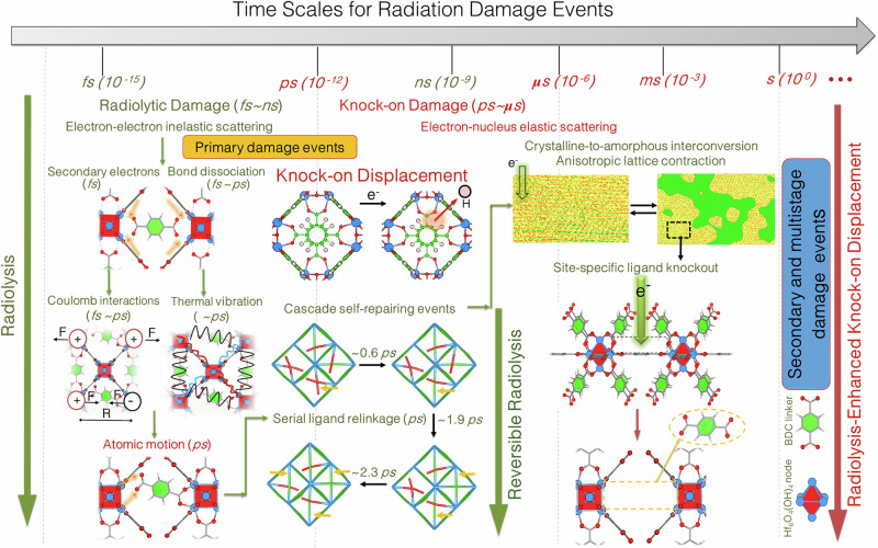
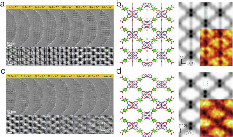
Recent advances in direct electron detectors and low-dose imaging techniques have opened up captivating possibilities for real-space visualization of radiation-induced structural dynamics. This has significantly contributed to our understanding of electron-beam radiation damage in materials, serving as the foundation for modern electron microscopy. In light of these developments, the exploration of more precise and specific beam damage mechanisms, along with the development of associated descriptive models, has expanded the theoretical framework of radiation damage beyond classical mechanisms. We unravel, in this work, the nonclassical beam damage mechanisms of an open-framework material, i.e. UiO-66(Hf) metal-organic framework, by integrating low-dose electron microscopy and ab initio simulations of radiation induced structural dynamics. The physical origins of radiation damage phenomena, spanning across multiple scales including morphological, lattice, and molecular levels, have been unequivocally unveiled. Based on these observations, potential alternative mechanisms including reversible radiolysis and radiolysis-enhanced knock-on displacement are proposed, which account for their respective dynamic crystalline-to-amorphous interconversion and site-specific ligand knockout events occurring during continuous beam radiation. The current study propels the fundamental understanding of beam damage mechanisms from dynamic and correlated perspectives. Moreover, it fuels technical innovations, such as low-dose ultrafast electron microscopy, enabling imaging of beam-sensitive materials with uncompromised spatial resolution.


Conflict of interest statement

Competing interests: The authors declare no competing interests.

Figures

Fig. 1
Fig. 1. The schematic illustration of radiation damage events and their time scales for MOFs UiO-66(Hf).
(i) The primary damage events including radiolytic damage (fs~ns) and knock-on displacement (ps~μs). The atomic motion arising from radiolytic damage is achieved by energy–momentum conversion through thermal vibration and/or local Coulomb repulsion effects. (ii) Nonclassical reversible radiolysis triggers cascade self-repairing events within the ps range, demonstrated by a simplified representation of UiO-66 structural model based on AIMD simulations. In this representation, blue dots refer to Hf6O4(OH)4 nodes, while red and green lines refer to broken and intact Hf–O bonds formed between BDC linkers and Hf6O4(OH)4 nodes respectively. The yellow arrows point to relinked Hf–O bonds in cascade self-repairing events. The yellow and green domains in the upper right part refer to dynamic crystalline-to-amorphous interconversion caused by nonclassical reversible radiolysis. (iii) The secondary and multistage damage events, including radiolysis-enhanced knock-on displacement events that account for the anisotropic lattice contraction and associated site-specific ligand knockout processes.
Fig. 2
Fig. 2. The elucidation of dose-rate effects from electron diffraction and kinetic model of nonclassical reversible radiolysis.
a Serial electron diffraction patterns collected over a [11¯0] projected UiO-66(Hf) crystal and under a dose rate of 1.0 e Å−2 s−1. b Radially averaged electron diffraction patterns and their projections spanning along accumulated electron dose. Red rectangular region refers to the profiled Bragg reflection at Q = 2.8 nm−1. c The exponential fitting of diffraction intensity decay curve as a function of accumulated electron dose. d Dose-rate effect calculated based on the kinetic model of nonclassical reversible radiolysis, which is plotted by dimensionless parameters for critical dose (m~) versus dose rate (n~), respectively. α refers to a dimensionless factor for the damage-to-repair ratio at unitary dose rate. The m~ value scales the critical dose for classical radiolysis while the n~ value scales the unitary dose rate.
Fig. 3
Fig. 3. Decoupling intergranular and intragranular deformations based on CG-SA and GPA methods.
a Schematic illustration of intergranular and intragranular deformations of an octahedral UiO-66(Hf) crystal under electron-beam radiation. b Demonstration of CG-SA method used for evaluating intergranular deformations, where rectangular ROIs are marked for measuring their relative displacements. Red and blue solid rectangles refer to original and displaced two crystalline ROIs connected by a predefined basis vector (solid red arrow). The displacement vectors are denoted by solid blue arrows. The auxiliary ROI and vectors are denoted by dashed rectangle and arrows to form a vector triangle that allows the determination of the deformation vector (solid yellow arrow). The predefined orthogonal x and y basis vectors are based on [110] and [001] axes respectively. c The evolutions of εxx [110], εyy [001], and εxy strain components for anisotropic deformation of UiO-66(Hf) crystals under different accumulated electron dose derived by CG-SA. d The evolution of εyy [001] strain component for intragranular deformations in UiO-66(Hf) crystals derived by GPA and rendered in temperature color code. The reference region for GPA analysis is marked by a white square.
Fig. 4
Fig. 4. Direct observation of molecular-level recrystallization process.
a Serial HRTEM images of UiO-66(Hf) crystals along the [11¯0] projection, after correcting CTF effects, under increasing accumulated electron dose in vacuum. be Magnified views of ROIs marked by white, yellow, blue, and green dashed rectangles in (a), accompanied by schematic illustrations of the structural models. The HRTEM images are rendered in a black-body false-color code. Blue represents the Hf6O4(OH)4 nodes, red indicates BDC linkers with broken bonds, and yellow indicates pristine BDC linkers.
Fig. 5
Fig. 5. Simulated cascade self-repairing steps dictated by nonclassical reversible radiolysis based on AIMD method.
a The simplified representation of structural models with multiple broken Hf–O bonds between BDC linkers and Hf6O4(OH)4 nodes and viewed along the [001] projection. The red rectangles refer to broken BDC linkers that undergo cascade self-repairing steps, the rest BDC linkers are denoted as yellow rectangles, and the blue square refers to Hf6O4(OH)4 nodes. b Time-dependent evolution of pPDFs for Hf–O pairs in serial trajectories simulated by AIMD. (left panel) pPDF profiles at (001) equatorial plane; (right panel) pPDF profiles along [001] direction. c The evolution of critical dose with different dose rates. The error bars are standard deviations. d The serial trajectories evolved during cascade self-repairing process. The recovery sequence of BDC linkers is numbered.
Fig. 6
Fig. 6. Regulation of nonclassical reversible radiolysis by introducing hydrogen atmosphere in environmental transmission electron microscope.
a The schematic of a dedicated ETEM equipped with a differential pumping vacuum system. b The schematic illustration of bond ionization followed by either inhibited or facilitated self-repairing events in hydrogen environment and vacuum respectively. The R* radical refers to O (red color) radical. c The dose series HRTEM images of the UiO-66(Hf) crystal in hydrogen atmosphere with a pressure of 5 mbar. The lattice contrast is enhanced by Bragg filtering. The crystalline-to-amorphous domains are rendered in a purple-blue-green false-color code.
Fig. 7
Fig. 7. Real-space visualization of site-specific ligand knockout events in UiO-66(Hf).
a, c Serial HRTEM images (upper) and enlarged regions (bottom) after correcting contrast inversion effects and taken under increasing accumulated electron dose over a UiO-66(Hf) crystal along the [11¯0] projection. The green circles denote the presence and absence of a BDC linker at an identical linker site under an electron dose of 8.0 e Å−2 and 64.7 e Å−2. b, d The structural models (left panels) and simulated projected potentials (right panels) for pristine and defective UiO-66(Hf) structures projected along the [11¯0] projection. The insets refer to corresponding contrast-corrected experimental HRTEM image motifs rendered in black-body color code.
Fig. 8
Fig. 8. Theoretical calculation of strain-dependent electronic structures and binding energies for radiolysis-enhanced knock-on displacement in UiO-66(Hf).
a The visualization of model-embedded HOMO orbitals for both unstrained and −15% strained UiO-66(Hf) structures along the [001] direction. b The relationship between Poisson’s ratio and magnitude of lattice expansion at the (001) equatorial plane. The calculated PDOS profiles of BDC linkers and Hf–O bonding sites between BDC linkers and Hf6O4(OH)4 nodes for c unstrained and d strained UiO-66(Hf) structures (i.e., −5%, −10%, and −15% strain along [001] direction). e The strain-dependent Hf–O binding energy of a BDC linker at the bridging site of a UiO-66(Hf) structure. f The calculated knock-on cross-section for O sites of BDC linkers bonded to the Hf6O4(OH)4 nodes, as a function of incident-electron energy under different Ed values.
Fig. 9
Fig. 9. Low-dose cryogenic HRTEM imaging and low-temperature radiation damage in UiO-66(Hf).
Schematic illustrations of a the electron optical system in an electron microscope. b cryogenic specimen transfer and imaging process for beam-sensitive materials at multiple temperature points by employing a custom-designed ultra-stable double-tilt cryo-transfer TEM holder. The structural models (left) and the contrast-corrected HRTEM image motifs (right) for c pristine and d defective UiO-66(Hf) structures. e Contrast-corrected HRTEM images of UiO-66(Hf) taken along the [11¯0] projection and at −196 °C, −50 °C, and 25 °C. Insets denote corresponding FFT patterns with their respective information transfer marked. f The measured critical doses at different temperatures under a dose rate of 1.0 e Å−2 s−1. The error bars are standard deviations.

Similar articles

Cited by

References

    1. Egerton, R. F., Li, P. & Malac, M. Radiation damage in the TEM and SEM. Micron35, 399–409 (2004). - PubMed
    1. Egerton, R. F. Choice of operating voltage for a transmission electron microscope. Ultramicroscopy145, 85–93 (2014). - PubMed
    1. Egerton, R. F. Radiation damage to organic and inorganic specimens in the TEM. Micron119, 72–87 (2019). - PubMed
    1. Bouchet, D. & Colliex, C. Experimental study of ELNES at grain boundaries in alumina: intergranular radiation damage effects on Al-L23 and O-K edges. Ultramicroscopy96, 139–152 (2003). - PubMed
    1. Vuković, F., Leyssale, J.-M., Aurel, P. & Marks, N. A. Evolution of threshold displacement energy in irradiated graphite. Phys. Rev. Appl.10, 064040 (2018).

LinkOut - more resources