Review
. 2025 Jan 3;15(1):167-198.
doi: 10.1039/d4ra05571c. eCollection 2025 Jan 2.

Microfluidic-based electrically driven particle manipulation techniques for biomedical applications

Affiliations
Review

Microfluidic-based electrically driven particle manipulation techniques for biomedical applications

Jiulin Wang et al. RSC Adv. .

Abstract

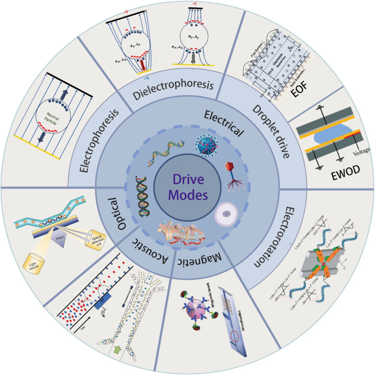
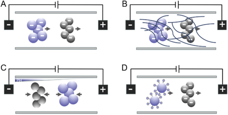
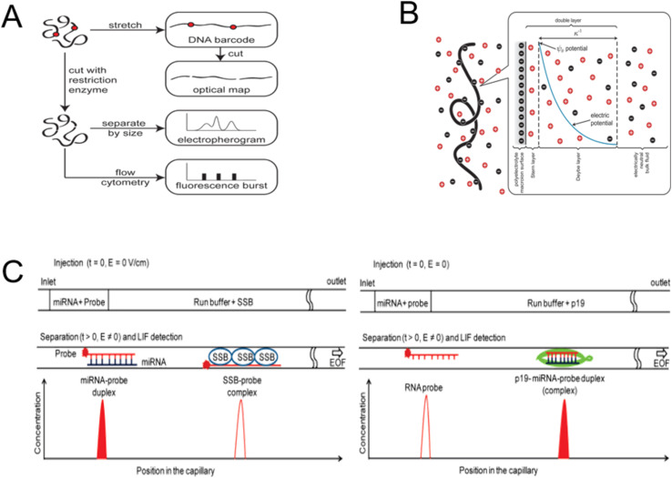
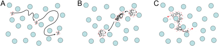
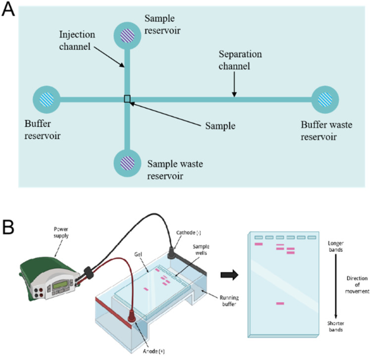
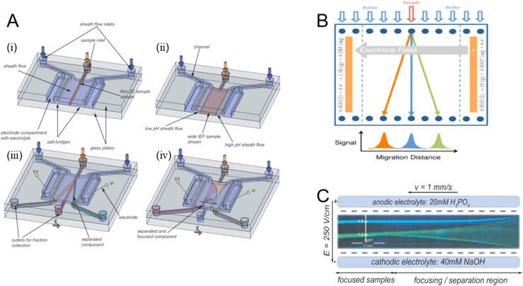
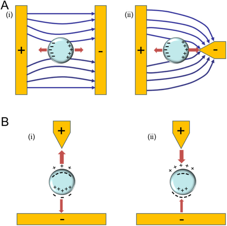
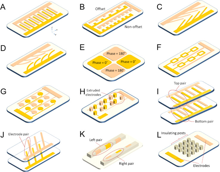
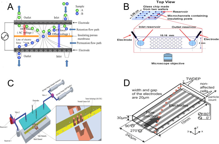
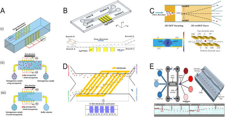
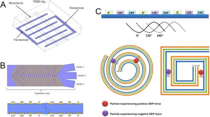
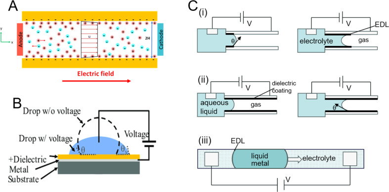
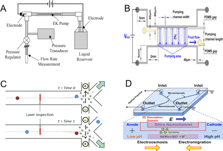
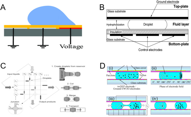
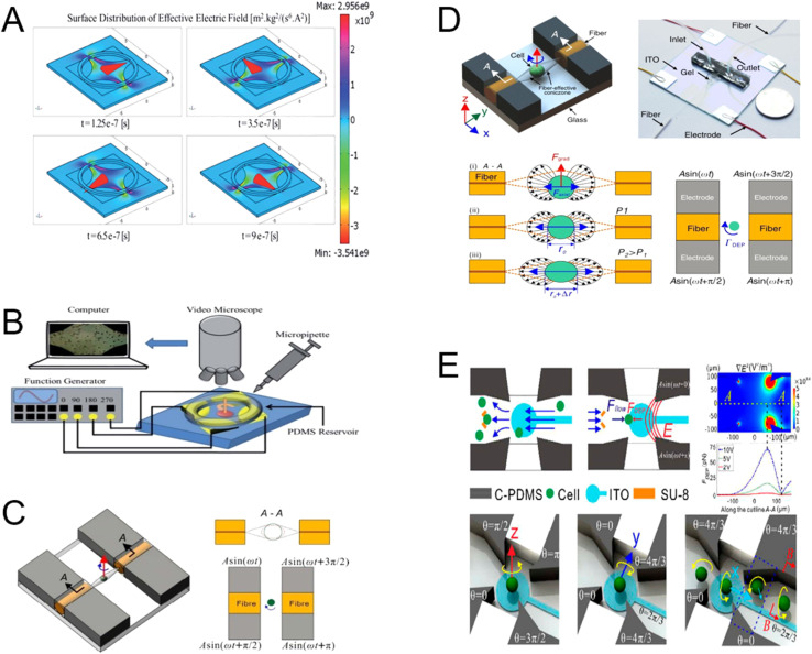
Microfluidic chips exhibit unique advantages in both economy and rapidity, particularly for the separation and detection of biomolecules. In this review, we first introduced the mechanisms of several electrically driven methods, such as electrophoresis, dielectrophoresis, electro-wetting and electro-rotation. We then discussed in detail the application of these methods in nucleic acid analysis, protein manipulation and cell treatment. In addition, we outlined the considerations for material selection, manufacturing processes and structural design of microfluidic chips based on electrically driven mechanisms.


Conflict of interest statement

The authors declare no competing interests.

Figures

Fig. 1
Fig. 1. An overview of the biological particle microfluidic drive techniques. The driving force of microfluidic techniques can be further subdivided into optical, acoustic, magnetic, and electrical forces. EOF: electroosmotic flow; EWOD: electrowetting-on-dielectric.
Fig. 2
Fig. 2. Electrophoresis modes used in microsystems: (A) free solution electrophoresis. (B) Gel electrophoresis. (C) Isoelectric focusing. (D) Micellar electrokinetic chromatography (with negatively charged analytes depicted).
Fig. 3
Fig. 3. Detection and separation of DNA using capillary electrophoresis. (A) The chip is made up of a chamber with inlets and a network of microchannels for CE analysis. (B) Diagram of the local electrostatics in the vicinity of a free-solution DNA coil. (C) The protein-facilitated affinity capillary electrophoresis (ProFACE) is used to detect miRNA.
Fig. 4
Fig. 4. DNA separation process utilizing gel electrophoresis. (A) Rg/a ≪ 1. (B) Rg/a ≈ 1 (C) Rg/a ≫ 1.
Fig. 5
Fig. 5. Schematic of the microfluidic gel electrophoresis apparatus. (A) Typical layout of miniaturized gel electrophoresis equipment. (B) A process diagram for distinguishing DNA by gel electrophoresis.
Fig. 6
Fig. 6. (A) An illustration of the m-FFE gadget and its separation mechanisms. (i and iii) Free-flow zone electrophoresis is applied. (ii and iv) Free-flow isoelectric focusing application. (B) General principle of separation in free-flow electrophoresis: the analyte's electrophoretic mobilities are used to deflect the sample stream laterally in an electric field as it is constantly supplied into the separation chamber. (C) Feasibility to direct the components to particular chip outlets by hydrodynamically concentrating the sample streams between two buffer streams and altering the inlet flow ratio of the two sheath flow streams.
Fig. 7
Fig. 7. Diagrams that illustrate the principle of DEP. (A) Positive dielectrophoretic (pDEP) diagram. (i) In a homogeneous electrical field, the particle is symmetrically polarized, producing a net DEP force (FDEP) with zero amplitude. (ii) The particle moves into an area with the largest amplitude of the electric field because it is asymmetrically polarized in the non-uniform electric field (NUEF) and the net FDEP. (B) A non-uniform electric field causes the dielectrophoretic force to act on the induced dipole: (i) positive DEP and (ii) negative DEP.
Fig. 8
Fig. 8. DEP devices categorized based on the arrangement of microelectrodes: (A) parallel or intersecting, (B) cylindrical, (C) angled, (D) curved, (E) quadrupole, (F) microporous, (G) matrix, (H) extruded, (I and J) top-down pattern, (K) sidewall pattern, and (L) insulator-based or nonpolar.
Fig. 9
Fig. 9. DEP device classification based on a few principles. (A) Diagram of the separation principle. (B) Chip schematic of proteins controlled by direct current (DC) field and insulator-based dielectric electrophoresis (IDEP). (C) The main channel (yellow) and side channel (pink) in the schematic of the cDEP device are connected by a very thin membrane. An electric field gradient forms in the main channel around the membrane when the conductive side channel is polarized using a linear electrode. (D) Using twDEP for separation.
Fig. 10
Fig. 10. Dielectrophoresis microfluidic chip design in three dimensions. (A) Electrodes on the side walls to provide a consistent electric field directed towards the channel height. (i) Diagram of the suggested microfluidic device; (ii) diagram of microparticle separation; (iii) diagram of microparticle aggregation. (B) PDMS microdevice with 3D sidewall composite electrodes and a built microdevice separation mechanism. (C) The 3D electrode design diagram. (D) Schematic of the design and principle for the microfluidic cell separation using continuous flow DEP. (E) Diagram of a microfluidic device that uses a focused flow to separate samples from consecutive non-uniformities in the field.
Fig. 11
Fig. 11. DEP structural design for biological applications. (A) Schematic of electrodes. (B) A chevron electrode configuration eliminating the erratic electric field and unexpected DEP and twDEP behaviours of the cells. (C) Spiral electrode array intended to create an electric field phase gradient in a three-phase travelling-wave DEP system.
Fig. 12
Fig. 12. Illustrations of DEP in biological contexts. (A) In microfluidic chips, alternating current DEP is used to collect double-stranded λ-DNA molecules between aluminum electrodes. (B) Working principle of employing DEP in a ramping electric field to isolate HeLa cells. (C) Bacterial cells trapped and accumulated for detection. When an electric field is generated, S. typhimurium is injected into a microfluidic channel and trapped at the detection region by pDEP. (D) CTC enrichment technique principle. A DEP force is applied to the cells, and as a result of the non-uniformity of the electric field is exposed on the bottom surface of each microwell in this design.
Fig. 13
Fig. 13. (A) Diagram showing the typical electroosmosis process in a microchannel. The electric double layer, which is predominant in cations, is subject to a tangential force from the electric field. The fluid travels as a result of this tangential force. (B) Typical external voltage EWOD setup to assess change in contact angle. (C) Driving principle comparison diagrams connected to EWOD: (i) electrowetting (EW). (ii) Electrowetting-on-dielectric (EWOD). (iii) Continuous electrowetting (CEW).
Fig. 14
Fig. 14. (A) Schematic of the setup for EOF micropump characterization. The volume flow rate in a tube is measured by pumping liquid with the EOF pump. (B) Schematic of the five-stage EOF pump. (C) Sorting of electroosmotic cells using direct current (DC). Solvated negative ions in the counterionic layer along the positively charged microchannel floor migrate to the oppositely charged electrode after laser inspection and cell identification. This causes the surrounding liquid to be drawn for cell transport to various outlets. (D) Proteins concentrated toward the anode (low pH) end when the electromigration effect is stronger and near the cathode (high pH) end when the electroosmotic effect is more prominent.
Fig. 15
Fig. 15. (A) Open coplanar EWOD design. (B) Diagram illustrating the cross-section of the electrowetting chip. The interfacial tension imbalance that results from applying an electric field to only one side of a droplet leads to the bulk flow of the droplet. (C) Envisioned digital microfluidic circuit that can be utilized as a lab-on-a-chip or micro total analysis device, together with the four essential droplet activities required: liquid droplets are created, transported, sliced, and merged using electrowetting techniques. (D) Procedures for separating particles within droplets using twDEP and EWOD.
Fig. 16
Fig. 16. (A) Effective electric field distribution on the device surface simulated by COMSOL. (B) Using microtubules, a 3 mL cell solution was added to the PDMS reservoir in the ER test setup. (C) Working principle of the microfluidic chip. Optical and electrical stretch devices rotate and stretch cells in particular directions. (D) Principles of electrospinning and the light-trapping and light-stretching process. (E) Operating principle of an ROT chip with 3D cells.

Similar articles

References

    1. Jiang J. Cui X. Huang Y. Yan D. Wang B. Yang Z. Chen M. Wang J. Zhang Y. Liu G. Advances and Prospects in Integrated Nano-oncology. Nano Biomed. Eng. 2024;16(2):152–187.
    1. Tian Q. Mu Y. Xu Y. Song Q. Yu B. Ma C. Jin W. Jin Q. An integrated microfluidic system for bovine DNA purification and digital PCR detection. Anal. Biochem. 2015;491:55–57. - PubMed
    1. Chen M. Lin S. Zhou C. Cui D. Haick H. Tang N. From conventional to microfluidic: progress in extracellular vesicle separation and individual characterization. Adv. Healthcare Mater. 2023;12(8):2202437. - PubMed
    1. Yatsushiro S. Yamaguchi Y. Yamamura S. Shinohara Y. Baba Y. Kataoka M. Highly sensitive DNA detection with a combination of 2 DNA-intercalating dyes for microchip electrophoresis. J. Pharm. Biomed. Anal. 2011;55(1):202–205. - PubMed
    1. Qian J.-J. Ji H.-Y. Cong H. Wang H.-M. Jin Q.-H. Application of Polydimethylsiloxane/Glass Microchips for Fast Electrophoretic Separation of Serum High-density Lipoprotein Subclasses. Chin. J. Anal. Chem. 2012;40(2):230–235.

LinkOut - more resources