Review
. 2024 Dec 28;25(1):133.
doi: 10.3390/s25010133.

Implantable Passive Sensors for Biomedical Applications

Affiliations
Review

Implantable Passive Sensors for Biomedical Applications

Panagiotis Kassanos et al. Sensors (Basel). .

Abstract

In recent years, implantable sensors have been extensively researched since they allow localized sensing at an area of interest (e.g., within the vicinity of a surgical site or other implant). They allow unobtrusive and potentially continuous sensing, enabling greater specificity, early warning capabilities, and thus timely clinical intervention. Wireless remote interrogation of the implanted sensor is typically achieved using radio frequency (RF), inductive coupling or ultrasound through an external device. Two categories of implantable sensors are available, namely active and passive. Active sensors offer greater capabilities, such as on-node signal and data processing, multiplexing and multimodal sensing, while also allowing lower detection limits, the possibility to encode patient sensitive information and bidirectional communication. However, they require an energy source to operate. Battery implantation, and maintenance, remains a very important constraint in many implantable applications even though energy can be provided wirelessly through the external device, in some cases. On the other hand, passive sensors offer the possibility of detection without the need for a local energy source or active electronics. They also offer significant advantages in the areas of system complexity, cost and size. In this review, implantable passive sensor technologies will be discussed along with their communication and readout schemes. Materials, detection strategies and clinical applications of passive sensors will be described. Advantages over active sensor technologies will be highlighted, as well as critical aspects related to packaging and biocompatibility.

Keywords: capacitive diaphragm; galvanic coupling; implantable sensors; inductive coupling; passive sensors; radiative coupling; ultrasonic coupling.


Conflict of interest statement

The authors declare no conflicts of interest.

Figures

Figure 5
Figure 5
Characteristic examples of flexible and stretchable passive, implantable strain sensors. (a) (i) Illustration of the architecture of the LC strain sensor for musculoskeletal applications proposed in [64], (ii) the fabricated device being twisted and (iii) the Au-TiO2 nanowires used to form the capacitive sensor plates. © 2023 The Authors. Distributed under the terms and conditions of the Creative Commons Attribution-Non Commercial-No Derivs License (CC BY-NC-ND 4.0) (https://creativecommons.org/licenses/by-nc-nd/4.0/, accessed on 23 December 2024). No changes were made. (b) (i) The LC strain sensor of [92]. It consists of helical electrodes to implement a parallel plate capacitor with an air gap between plates that was also exploited to aid the suturing of the device in connective tissue. (ii) Measurement spectra of S11 for applied tensile strains up to 40%. Large resonant frequency shifts were achieved with the proposed device. Reproduced with permission from Springer Nature. Published in Nature Electronics (https://www.nature.com/natelectron/, accessed on 23 December 2024). (c) A similar LC strain-sensing device by the same group targeting bladder volume monitoring [93]. Illustrations of the (i) use of the device and (ii) its operational principle, (iii) the external interrogating device, (iv) the implantable device and (v) the pressure-sensing parallel plate capacitor. © 2018 WILEY-VCH Verlag GmbH & Co. KGaA, Weinheim. Reproduced with permission from John Wiley and Sons. (d) The metamaterial-based flexible permanent strain-sensing device developed for orthopedic applications with a nested split ring resonator topology [94]. (i) Illustration of the device architecture and geometry. (ii) The fabricated device. Inset: Close-up of the top and bottom fingers of the device. Reprinted from Sensors and Actuators A: Physical, Vol 255, A. Alipour, E. Unal, S. Gokyar, H. V. Demir, Development of a distance-independent wireless passive RF resonator sensor and a new telemetric measurement technique for wireless strain monitoring, Pages 87–93, Copyright (2017), with permission from Elsevier.
Figure 1
Figure 1
Comparison of active and passive implantable devices.
Figure 2
Figure 2
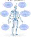
Representative applications of passive implantable sensors. These can be interrogated using ultrasonic (using piezoelectric transducers), inductive (using inductors) or radiative coupling (using antennas). Background human image by @migstc1, from Freepik Company S.L. Malaga, Spain (www.freepik.com, accessed on 22 October 2024).
Figure 3
Figure 3
Examples of passive implantable pressure sensors based on the capacitance change caused by a deflection of a membrane. These types of sensors are referred to as MEMS (Micro Electro-Mechanical System)-type in the text. (a) The biodegradable and flexible arterial-pulse pressure sensor of [58]. Reproduced with permission from Springer Nature. Published in Nature Biomedical Engineering (https://www.nature.com/natbiomedeng/, accessed on 23 December 2024). (i) Close-up illustration of the pressure-sensitive area with the two variable capacitors, before the sensor is wrapped around the artery. (ii) The fabricated device and close-ups of the double capacitor sensing region of the device and the pyramid-shaped microstructured sensing layer. (b) The biodegradable wireless LC pressure sensor of [60]. Notable is the use of wax and conductive composite wax, among other novelties. © 2020 Wiley-VCH GmbH. Reproduced with permission from John Wiley and Sons. (c) The biodegradable PDLA-based wireless LC pressure sensor of [59], formed by folding the device and adding an intermediate insulating spacer that defines the diaphragm. (i) Before assembly. (ii) after assembly and (iii) magnification of the capacitor and inductor of the sensor. Reprinted from Microelectronic Engineering, Vol 206, J. Park, J.-K. Kim, S. A. Park, D.-W. Lee, Biodegradable polymer material based smart stent: Wireless pressure sensor and 3D printed stent, Pages 1–5, Copyright (2019), with permission from Elsevier. (d) The SAW resonator-based pressure sensor of [61]. © The Authors 2013. Distributed under the terms and conditions of the Creative Commons Attribution (CC BY) license (https://creativecommons.org/licenses/by/4.0/, accessed on 23 December 2024). No changes were made.
Figure 4
Figure 4
Examples of passive implantable capacitive pressure sensors based on soft, deformable dielectric layers and structured elastomers and diaphragms. (a) The degradable LC pressure sensor of [55]. It consists of layers of a composite silk fibroin protein film (SFPF) as the sensor substrate and intermediate dielectric and a hydrogel silk fibroin elastomer as the dielectric layer of the capacitor. Mg is used as the conductor. © 2023 The Authors. Distributed under the terms and conditions of the Creative Commons Attribution (CC BY) license (https://creativecommons.org/licenses/by/4.0/, accessed on 23 December 2024). No changes were made. (b) The permanent LC pressure sensor of [84] and the pyramidal-structured capacitor dielectric layer of the device. Reproduced with permission from Springer Nature. Published in Nature Communications (https://www.nature.com/ncomms/, accessed on 23 December 2024). (c) The bioresorbable pressure sensor of [85] and its cross-section. Mg is used once again as the conductor. © 2019 WILEY-VCH Verlag GmbH & Co. KGaA, Weinheim. Reproduced with permission from John Wiley and Sons.
Figure 6
Figure 6
Examples of passive implantable sensors that utilize different material properties for the detection of pH, temperature and glucose through changes in polymer or hydrogel properties. (a) The bioresorbable pH sensor for gastric leakage detection of [53]. The device consists of a serpentine spiral inductor, which is encased within a pH-responsive hydrogel. The circuit is completed with a wax-encapsulated capacitor. Copyright © 2024 The Authors. Distributed under the terms and conditions of the Creative Commons Attribution (CC BY 4.0) license (https://creativecommons.org/licenses/by/4.0/). No changes were made. (b) An acoustic metamaterial-based temperature sensor [70]. Temperature variations change the bulk modulus of PDMS and Si, producing a shift in the resonance frequency. (i) The fabrication process of the device. Steps include deep reactive ion etching (DRIE) of a 4-inch, 500 μm-thick Si wafer and coating of polydimethylsiloxane (PDMS) as a polymeric matrix. (ii) The fabricated device. (iii) Scanning electron microscopy (SEM) details of the fabricated silicon micropillars. The micropillars had a nominal height of 350 μm and nominal radius of 35 μm. (iv) The unit cell and its arrangement. © The Authors 2024. Distributed under the terms and conditions of the Creative Commons Attribution (CC BY 4.0) license (https://creativecommons.org/licenses/by/4.0/). No Changes were made. (c) The temperature sensor proposed in [71], consisting of an LC circuit with a temperature-sensitive PEG capacitor. The images show the in vitro biodegradation process of the device in PBS at 37 °C. © 2020 WILEY-VCH Verlag GmbH & Co. KGaA, Weinheim. Reproduced with permission from John Wiley and Sons. (d) The passive hydrogel-based glucose sensor demonstrated in [66]. (i) Illustration of the structure of the device and the broad-side coupled, split-ring resonator interceded by the p(PBA-co-AAm) hydrogel interlayer. (ii) Illustration of the swelling induced to the interlayer in the presence of glucose binding with PBA. Swelling of the interlayer and changes in its thickness, changes the capacitance of the resonator. Upon glucose uptake, the hydrogel swells, increasing the capacitance of the device. Reprinted from Biosensors and Bioelectronics, Vol 151, M. Dautta, M. Alshetaiwi, J. Escobar, P. Tseng, Passive and wireless, implantable glucose sensing with phenylboronic acid hydrogel-interlayer RF resonators, Pages 112004, Copyright (2020), with permission from Elsevier.
Figure 7
Figure 7
Examples of different approaches for measuring bio-potentials, where backscattering is exploited, as well as varactors or single transistors and ultrasonics for measuring voltage signals. (a) (i) Illustration of the architecture and the use of a flexible permanent passive device capable of measuring voltages through the use of a varactor. It mixes the radio frequency (RF) carrier signal with the neuropotentials to create third order products. The signal is then backscattered to the external interrogator. Filtering and demodulation allow extraction of the neuropotentials. (ii)_Schematic of the implantable device and of the external interrogator [72]. Reprinted with permission from S. Liu et al., “Fully Passive Flexible Wireless Neural Recorder for the Acquisition of Neuropotentials from a Rat Model,” ACS Sens., vol. 4, no. 12, pp. 3175–3185, Dec. 2019, doi: 10.1021/acssensors.9b01491. Copyright 2019 American Chemical Society. (b) Another example of a passive device capable of recording electrophysiological signals [124]. (i) Architecture and operational principle of the device. (ii) Schematic of the architecture of the external interrogator and (iii) the implanted device. (iv) Images of the fabricated flexible sensor. Reprinted from Biosensors and Bioelectronics, Vol 139, S. Liu, X. Meng, J. Zhang, J. Chae, A wireless fully-passive acquisition of biopotentials, Pages 111336, Copyright (2019), with permission from Elsevier. (c) The ultrasonic neural dust approach from [128], where following a pulsed excitation, the backscattered signal is recorded and analyzed to extract the neural signal. (i) Architecture of the system. (ii) Image of the implanted device. (iii) Side image of the device. Reprinted from Neuron, Vol 91, D. Seo, R. M. Neely, K. Shen, U. Singhal, E. Alon, J. M. Rabaey, J. M. Carmena, M. M. Maharbiz, Wireless Recording in the Peripheral Nervous System with Ultrasonic Neural Dust, Pages 529–539, Copyright (2016), with permission from Elsevier. (d) The approach proposed in [129] to record differential electrophysiological signals. Similarly to the neural dust approach, transistors are used. Copyright © 2023 The Authors. Distributed under the terms and conditions of the Creative Commons Attribution (CC BY 4.0) license (https://creativecommons.org/licenses/by/4.0/, accessed on 23 December 2024). No changes were made.
Figure 8
Figure 8
(a) Measurement of the impedance from the external primary coil. (b) Measurement using a pulsed transient approach. Adapted from [207].

References

    1. Sazonov E. Wearable Sensors: Fundamentals, Implementation and Applications. 2nd ed. Academic Press; Cambridge, MA, USA: 2020.
    1. Yang G.-Z., editor. Implantable Sensors and Systems: From Theory to Practice. Springer; Berlin, Germany: 2018.
    1. Ghaffari R., Rogers J.A., Ray T.R. Recent Progress, Challenges, and Opportunities for Wearable Biochemical Sensors for Sweat Analysis. Sens. Actuators B Chem. 2021;332:129447. doi: 10.1016/j.snb.2021.129447. - DOI - PMC - PubMed
    1. Liu Y., Pharr M., Salvatore G.A. Lab-on-Skin: A Review of Flexible and Stretchable Electronics for Wearable Health Monitoring. ACS Nano. 2017;11:9614–9635. doi: 10.1021/acsnano.7b04898. - DOI - PubMed
    1. Beck H., Boden W.E., Patibandla S., Kireyev D., Gupta V., Campagna F., Cain M.E., Marine J.E. 50th Anniversary of the First Successful Permanent Pacemaker Implantation in the United States: Historical Review and Future Directions. Am. J. Cardiol. 2010;106:810–818. doi: 10.1016/j.amjcard.2010.04.043. - DOI - PubMed

MeSH terms

LinkOut - more resources