Review
. 2024 Nov 27;5(1):88-114.
doi: 10.1021/acsmaterialsau.4c00122. eCollection 2025 Jan 8.

A Comprehensive Review on Polymer-Dispersed Liquid Crystals: Mechanisms, Materials, and Applications

Affiliations
Review

A Comprehensive Review on Polymer-Dispersed Liquid Crystals: Mechanisms, Materials, and Applications

Shikha Agarwal et al. ACS Mater Au. .

Abstract

Polymer-dispersed liquid crystals (PDLCs) stand at the intersection of polymer science and liquid crystal technology, offering a unique blend of optical versatility and mechanical durability. These composite materials are composed of droplets of liquid crystals interspersed in a matrix of polymeric materials, harnessing the optical properties of liquid crystals while benefiting from the structural integrity of polymers. The responsiveness of LCs combined with the mechanical rigidity of polymers make polymer/LC composites-where the polymer network or matrix is used to stabilize and modify the LC phase-extremely important for scientists developing novel adaptive optical devices. PDLCs have garnered significant attention due to their ability to modulate light transmission properties, making them ideal candidates for applications ranging from smart windows and displays to light shutters and privacy filters. The incorporation of different ferroelectric, thermoelectric, magnetic, and ferromagnetic nanoparticles, quantum dots, nanorods, and a variety of dyes in the PDLC matrix has gained momentum over a span of few decades, as it lowers the otherwise-required high operating voltage and reduces the electro-optical response time of these devices. Due to better contrast in the transmittance of these materials in the field-off and on states, they find extensively wide application in a variety of photonic applications, viz., optical shutters and smart windows, photorefractives, modern displays, microlens arrays encompassing polymer-gravel lenses, and many other. Since the functional parameters of these devices embrace the thermophysical attributes of PDLC networks, it therefore becomes necessary to perform a detailed analysis of the properties of PDLCs and their ameliorations upon the addition of different dopants. This Review aims to review the recent advances in PDLCs and their enrichment in terms of their performance parameters upon the addition of a variety of dopants, as well as the improvement of different photonic applications owing to superior parametric implementation of these networks.


Conflict of interest statement

The authors declare no competing financial interest.

Figures

Figure 1
Figure 1
Classification chart of LC–polymer composite systems.
Figure 2
Figure 2
SEM images exhibiting the morphology of (a) a polymer-dispersed liquid crystal and (b) a polymer-stabilized liquid crystal. (a) Reproduced from ref (33). Available under a CC-BY license. Copyright 2019 H-Q Zhang and H. Yang et al. (b) Adapted with permission from ref (34). Copyright 1996 American Chemical Society.
Figure 3
Figure 3
(a, b) Schematic representation of normal-mode PDLC in (a) OFF-state and (b) ON-state. (c, d) Schematic representation of reverse-mode PDLC in (c) OFF-state and (d) ON-state.
Figure 4
Figure 4
Different configurations of nematic droplets in PDLCs: (a) bipolar structure, (b) toroidal structure, (c) radial structure, and (d) axial structure.
Figure 5
Figure 5
(a–d) Transition of droplet configuration from (a) bipolar (in the absence of an electric field) to (d) radial (at ∼25 Vp–p) configuration with increasing electric field. Reproduced with permission from ref (108). Copyright 2004 Elsevier.
Figure 6
Figure 6
Schematic stepwise illustrations of different techniques used for creating phase separation in a PDLC system: (a) polymerization-induced phase separation (PIPS), (b) solution-induced phase separation (SIPS), (c) temperature-induced phase separation (TIPS), and (d) encapsulation.
Figure 7
Figure 7
Schematic illustrations of different polymer structures: (a) linear, (b) branched, and (c) cross-linked polymer structures.
Figure 8
Figure 8
Different polymerization reactions and schematics of their related kinetic schemes. (a) Addition polymerization, in which a free radical (I•) is formed due to thermal or photoinitiated activation of the initiator (I). This free radical reacts with the species R and activates it to (R•), which further combines with the monomer M and causes rapid chain growth. (b) Step-polymerization (schematic for the reaction between monomers with reactive groups X and Y). (c) Ring-opening polymerization (reaction scheme for conversion of glycolide to polyglycolide).
Figure 9
Figure 9
Molecular structures of some monomers that undergo addition polymerization and are commonly employed in PDLC films: (a) n-butyl acrylate, (b) methyl methacrylate, and (c) vinyl acetate. The first two are generally used in the PIPS process, while the third one acts as a precursor of poly(vinyl alcohol) for emulsion-based systems.
Figure 10
Figure 10
Pictorial representation of the film preparation. (a) Homogeneous isotropic mixture positioned between two plastic sheet pieces (b) The liquid crystalline mixture and polymer matrix undergo a microphase separation. (c) Random orientation of LC mixture within a particular droplet (d) Homeotropic alignment of LC mixture. (f) Slow conversion of N* phase into SmA phase upon utilization of monomers that are photopolymerizable. (g) Homeotropic alignment of the SmA phase within a LC droplet. (h) The focal-conic texture exhibiting the formation of N* phase within LC droplets due to induction by heat. (i, j) Photographs of the film (at temperature lower than the TNI) in the transparent and opaque states, respectively. Reprinted with permission from ref (208). Copyright 2017 American Chemical Society.
Figure 11
Figure 11
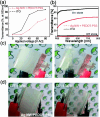
(a) Transmittance of PDLC-based smart window was a function of applied voltage. (b) On and off-state transmittance of a PDLC-based smart window for the two different type of electrode materials as a function of wavelength. Photographs of PDLC-based smart windows in the off and on-state (c) with ITO electrodes and (d) with Ag NW/PEDOT:PSS hybrid TSEs. Reproduced from ref (222). Available under a CC-BY 3.0 license. Copyright 2018 J. Park and H. Kim.
Figure 12
Figure 12
PDLC device developed using the vacuum-glass coupling technique: (a) opaque in off state and (b) transparent in on state. The corresponding change in the transmittance of the device as a function of (c) the applied voltage and (d) the angle of incidence of light. Reproduced with permission from ref (223). Available under a CC-BY 3.0 license. Copyright 2020 Y. Seo et al.
Figure 13
Figure 13
Sensing capabilities using weak gas flow stimulations and mechanism. (a) Variation of drain current (ID) with time under stimulation with nitrogen gas flows (gas intensity of 0.3–5.0 sccm for 5 s) for the flexible PDLC-i-OFET devices. (b) Variation of drain current change (ΔID) with gas intensity before and after nitrogen gas stimulations. (c) Change of 5CB alignment in the channel region of PDLC-i-OFET devices as per variations in applied voltages and nitrogen gas stimulations: (top) polarized optical microscope images and (bottom) illustrations of the possible orientation of 5CB molecules in the LC microdots in the channel layers. Reproduced with permission from ref (253). Available under a CC-BY 4.0 license. Copyright 2017 Kim et al.

Similar articles

Cited by

References

    1. Lin Y.-H.; Wang Y.-J.; Reshetnyak V. Liquid crystal lenses with tunable focal length. Liquid Crystals Reviews 2017, 5 (2), 111–143. 10.1080/21680396.2018.1440256. - DOI
    1. Kim T. H.; Kim M.; Manda R.; Lim Y. J.; Cho K. J.; Hee H.; Kang J.-W.; Lee G.-D.; Lee S. H. Flexible Liquid Crystal Displays Using Liquid Crystal-polymer Composite Film and Colorless Polyimide Substrate. Curr. Opt. Photon. 2019, 3 (1), 66–71.
    1. Choi H.-M.; Choi J.-G.; Kim E.-S. Dual-View Three-Dimensional Display Based on Direct-Projection Integral Imaging with Convex Mirror Arrays. Applied Sciences 2019, 9 (8), 1577.10.3390/app9081577. - DOI
    1. Moser S.; Ritsch-Marte M.; Thalhammer G. Model-based compensation of pixel crosstalk in liquid crystal spatial light modulators. Opt. Express 2019, 27 (18), 25046–25063. 10.1364/OE.27.025046. - DOI - PubMed
    1. Schadt M. D. Nematic liquid crystals and twisted-nematic LCDs. Liq. Cryst. 2015, 42, 646–652. 10.1080/02678292.2015.1021597. - DOI

LinkOut - more resources