

Design, modeling, and preliminary evaluation of a simple wrist-hand stretching orthosis for neurologically impaired patients
- PMID: 39811478
- PMCID: PMC11729525
- DOI: 10.1017/wtc.2024.22
Design, modeling, and preliminary evaluation of a simple wrist-hand stretching orthosis for neurologically impaired patients
Abstract
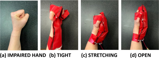
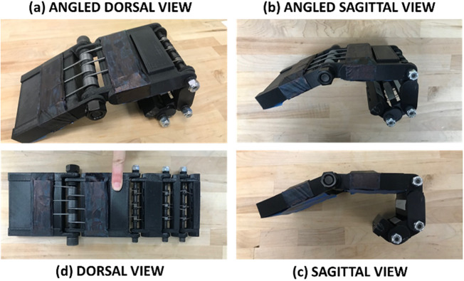
This work studies upper-limb impairment resulting from stroke or traumatic brain injury and presents a simple technological solution for a subset of patients: a soft, active stretching aid for at-home use. To better understand the issues associated with existing associated rehabilitation devices, customer discovery conversations were conducted with 153 people in the healthcare ecosystem (60 patients, 30 caregivers, and 63 medical providers). These patients fell into two populations: spastic (stiff, clenched hands) and flaccid (limp hands). Focusing on the first category, a set of design constraints was developed based on the information collected from the customer discovery. With these constraints in mind, a powered wrist-hand stretching orthosis (exoskeleton) was designed and prototyped as a preclinical study (T0 basic science research) to aid in recovery. The orthosis was tested on two patients for proof-of-concept, one survivor of stroke and one of traumatic brain injury. The prototype was able to consistently open both patients' hands. A mathematical model was developed to characterize joint stiffness based on experimental testing. Donning and doffing times for the prototype averaged 76 and 12.5 s, respectively, for each subject unassisted. This compared favorably to times shown in the literature. This device benefits from simple construction and low-cost materials and is envisioned to become a therapy device accessible to patients in the home. This work lays the foundation for phase 1 clinical trials and further device development.
Keywords: Intelligent orthotics; Rehabilitation robotics.
© The Author(s) 2024.
Conflict of interest statement
None.
Figures


Similar articles
-
Design, modeling, and preliminary evaluation of a 3D-printed wrist-hand grasping orthosis for stroke survivors.Wearable Technol. 2024 Nov 8;5:e12. doi: 10.1017/wtc.2024.18. eCollection 2024. Wearable Technol. 2024. PMID: 39575325 Free PMC article.
-
Characterization and wearability evaluation of a fully portable wrist exoskeleton for unsupervised training after stroke.J Neuroeng Rehabil. 2020 Oct 7;17(1):132. doi: 10.1186/s12984-020-00749-4. J Neuroeng Rehabil. 2020. PMID: 33028354 Free PMC article.
-
Giving Them a Hand: Wearing a Myoelectric Elbow-Wrist-Hand Orthosis Reduces Upper Extremity Impairment in Chronic Stroke.Arch Phys Med Rehabil. 2017 Sep;98(9):1821-1827. doi: 10.1016/j.apmr.2016.12.016. Epub 2017 Jan 25. Arch Phys Med Rehabil. 2017. PMID: 28130084
-
Home-based upper limb stroke rehabilitation mechatronics: challenges and opportunities.Biomed Eng Online. 2023 Jul 9;22(1):67. doi: 10.1186/s12938-023-01133-8. Biomed Eng Online. 2023. PMID: 37424017 Free PMC article. Review.
-
Personal protective equipment for preventing highly infectious diseases due to exposure to contaminated body fluids in healthcare staff.Cochrane Database Syst Rev. 2020 Apr 15;4(4):CD011621. doi: 10.1002/14651858.CD011621.pub4. Cochrane Database Syst Rev. 2020. Update in: Cochrane Database Syst Rev. 2020 May 15;5:CD011621. doi: 10.1002/14651858.CD011621.pub5. PMID: 32293717 Free PMC article. Updated.
References
-
- Ates S, et al. (2015) Combined active wrist and hand orthosis for home use: lessons learned. In IEEE ICORR. 10.1109/ICORR.2015.7281232 - DOI
-
- Baumgarte J (1972) Stabilization of constraints and integrals of motion in dynamical systems. Computer Methods in Applied Mechanics and Engineering, 1(1), 1–16.
-
- Bioness (2024) H200 for hand paralysis, Product Information, Encompass Health Corporation.
-
- BTL Robotics (2024). R-Lead: Neurocognitive Training for Upper Limbs, BTL Corporate, https://www.btlnet.com/r-lead.
LinkOut - more resources
Full Text Sources