. 2025 Jan 9;12(1):014301.
doi: 10.1063/4.0000275. eCollection 2025 Jan.

Convergent-beam attosecond x-ray crystallography

Affiliations

Convergent-beam attosecond x-ray crystallography

Henry N Chapman et al. Struct Dyn. .

Abstract

Sub-ångström spatial resolution of electron density coupled with sub-femtosecond to few-femtosecond temporal resolution is required to directly observe the dynamics of the electronic structure of a molecule after photoinitiation or some other ultrafast perturbation, such as by soft X-rays. Meeting this challenge, pushing the field of quantum crystallography to attosecond timescales, would bring insights into how the electronic and nuclear degrees of freedom couple, enable the study of quantum coherences involved in molecular dynamics, and ultimately enable these dynamics to be controlled. Here, we propose to reach this realm by employing convergent-beam x-ray crystallography with high-power attosecond pulses from a hard-x-ray free-electron laser. We show that with dispersive optics, such as multilayer Laue lenses of high numerical aperture, it becomes possible to encode time into the resulting diffraction pattern with deep sub-femtosecond precision. Each snapshot diffraction pattern consists of Bragg streaks that can be mapped back to arrival times and positions of X-rays on the face of a crystal. This can span tens of femtoseconds and can be finely sampled as we demonstrate experimentally. The approach brings several other advantages, such as an increase in the number of observable reflections in a snapshot diffraction pattern, all fully integrated, to improve the speed and accuracy of serial crystallography-especially for crystals of small molecules.


Conflict of interest statement

The authors have no conflicts to disclose.

Figures

FIG. 1.
FIG. 1.
Convergent beam diffraction from a thick crystal in focus (a) occurs within the volume of the crystal intersected by the focused beam. When out of focus (b), diffraction occurs at the positions intersected by the particular kin vectors (blue) that fulfill the diffracting condition. (c) In both cases, the diffracting condition is determined by the orientation of the Ewald sphere intersecting the reciprocal lattice vector qhkl. (d) The condition is invariant to rotation around the qhkl vector and so the diffracting and incident vectors describe a circle in the plane normal to and bisecting qhkl. Given the available kin supplied by the lens aperture A(kin), these vectors are confined to the surface of a cone, with its apex at the origin, and sweep out arcs (bold lines).
FIG. 2.
FIG. 2.
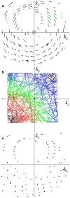
(a) Simulated convergent-beam diffraction pattern showing positions of Bragg streaks to a resolution of 1.5 Å (in the corners of the pattern) at a wavelength of 1 Å with an off-axis lens with a square aperture, NA = 0.035, and for an orthorhombic lattice with unit cell parameters a = 9.0 Å, b =15.7 Å, c = 18.8 Å. The center of the pattern shows the transmitted deficit lines that map out the lens pupil and are shown magnified in (b). The deficit lines and Bragg streaks are colored according to the transverse distance in the lens pupil from the bottom left corner. Black circles indicate the positions of Bragg peaks that would be seen if the NA was reduced to 0.001. (c) Laue diffraction pattern obtained from the same crystal lattice with a relative bandwidth of 25%. In this case the color represents wavelength, ranging from 0.87 Å (dark blue) to 1.12 Å (dark red).
FIG. 3.
FIG. 3.
Convergent-beam diffraction patterns intersect large volumes of reciprocal space, comparable to high-bandwidth Laue diffraction. (a) The participating volume of reciprocal space in convergent-beam diffraction lies between Ewald spheres centered on the range of kin vectors, shown shaded in blue. When considering diffraction extending to a maximum angle 2θ, only the region shaded in the dark blue participates. This volume is a fraction of the full volume of resolution-limited reciprocal space (indicated by the green shading), referred to as the relative volume. (b) Similarly, for Laue diffraction, the dark orange volume is the participating volume of reciprocal space for a given maximum scattering angle. (c) The relative volumes are plotted as a function of the resolution for NA=0.035 convergent-beam diffraction (blue) and for a relative bandwidth of 25% for Laue diffraction (orange). (d) The relative volumes for 2θ=45° ( 2sinθ=0.7), plotted as a function of the lens NA or relative bandwidth.
FIG. 4.
FIG. 4.
(a) A short collimated pulse focused by a dispersive lens lags behind the phase front by a time Δf/c that depends quadratically on the angle ϕ of the ray with the optical axis, shown here for a diffractive lens with a dispersive power of V = – 1. Rays, thus, arrive at the focus with this delay. For a flat crystal placed a distance z downstream of focus, the rays require an additional time of Δz/c to pass the face of the crystal. For a plane wave pump pulse that arrives simultaneously across the crystal face, the pump-probe delay T will vary with arrival time of the probe pulse on the crystal TX, given in (b). An inclined pump pulse (c), or one with a tilted pulse front, also maps arrival times Tp to position, extending the range of delay times to T=TXTp (d).
FIG. 5.
FIG. 5.
Orientations of the crystal, pump, and probe pulses required to maintain the delay between the pump pulse (red) and focused x-ray beam (black), along the path of the x-ray beam as it propagates through the crystal with a refractive index np>1 for the pump and nX = 1 for the probe. Phase fronts of the x-ray pulse and the pump pulse are indicated by blue and red dashed lines, respectively. No pulse tilt is assumed. (a) Pump pulse incident normal to the crystal face. (b) Pump pulse refracted by the crystal face.
FIG. 6.
FIG. 6.
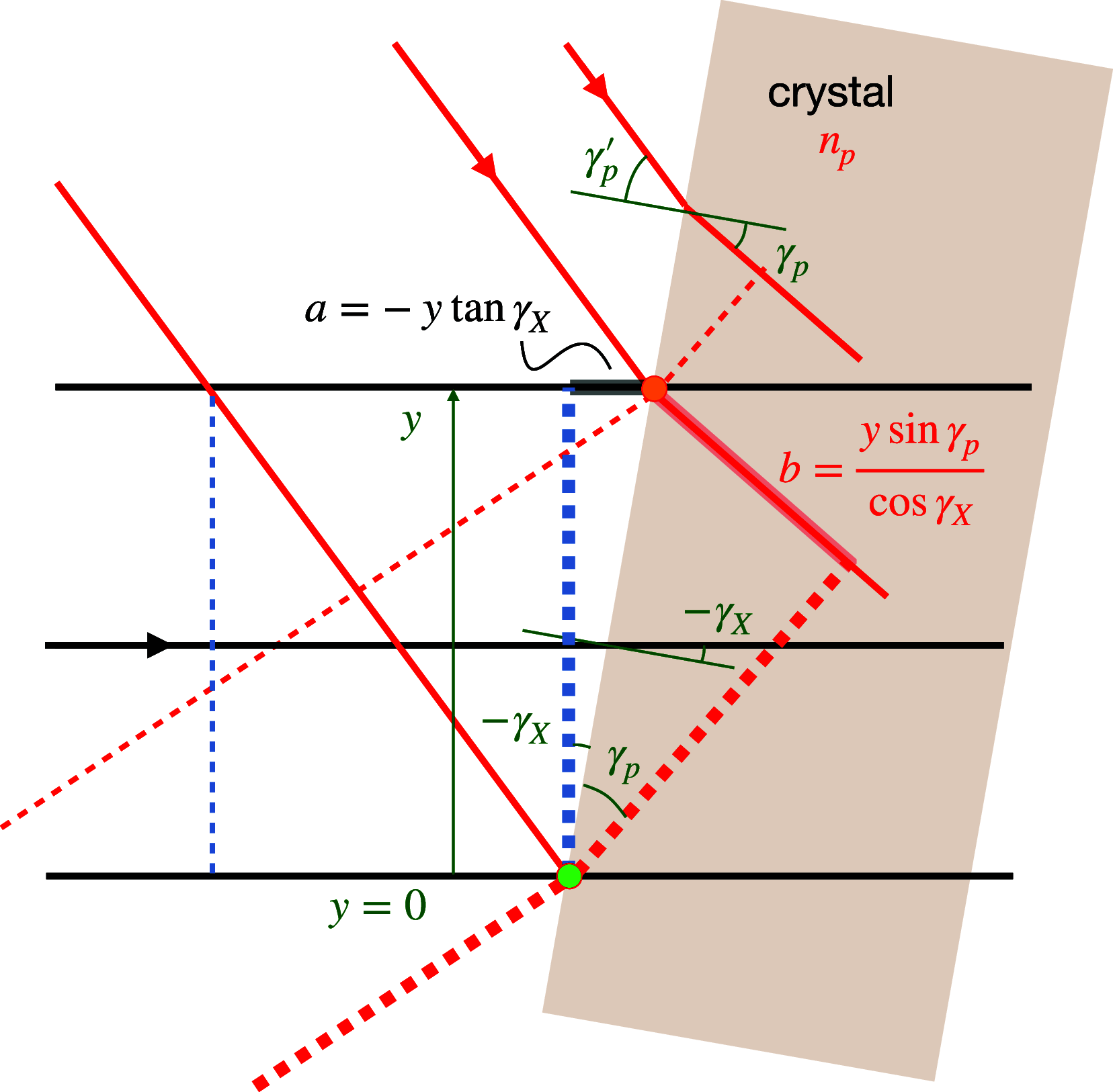
Geometry of crossed-beam topography for the same velocity matching conditions as Fig. 5(b), ignoring the convergence of the x-ray beam. The pump pulse (red rays) and x-ray pulse (black rays) coincide in time at the surface of the crystal at the green circle at a height y = 0. The x-ray pulse arrives later at the crystal at height y after a time TX(y)=a/c, at which point the pump pulse has already traveled a distance b in the medium of refractive index np, giving an arrival time of Tp(y)=bnp/c.
FIG. 7.
FIG. 7.
(a) Diffraction from a single vitamin B12 crystal placed 3.5 mm downstream of the focus of a 0.028 NA lens at a photon energy of 17.5 keV. The red circle indicates a resolution of 1 Å. The region outlined with dashed lines is shown enlarged in (b). (c) Map of the deficit lines obtained from the Bragg streaks of (a). (d) Map of the projected crystal diffraction efficiency obtained from integrating the 412 Bragg streak, highlighted in (b), over a 2.75° fine rotation scan of the crystal about the vertical axis.

References

    1. Brändén G. and Neutze R., “ Advances and challenges in time-resolved macromolecular crystallography,” Science 373, eaba0954 (2021).10.1126/science.aba0954 - DOI - PubMed
    1. Khusainov G., Standfuss J., and Weinert T., “ The time revolution in macromolecular crystallography,” Struct. Dyn. 11, 020901 (2024).10.1063/4.0000247 - DOI - PMC - PubMed
    1. Dods R., Båth P., Morozov D., Gagnér V. A., Arnlund D., Luk H. L., Kübel J., Maj M., Vallejos A., Wickstrand C., Bosman R., Beyerlein K. R., Nelson G., Liang M., Milathianaki D., Robinson J., Harimoorthy R., Berntsen P., Malmerberg E., Johansson L., Andersson R., Carbajo S., Claesson E., Conrad C. E., Dahl P., Hammarin G., Hunter M. S., Li C., Lisova S., Royant A., Safari C., Sharma A., Williams G. J., Yefanov O., Westenhoff S., Davidsson J., DePonte D. P., Boutet S., Barty A., Katona G., Groenhof G., Brändén G., and Neutze R., “ Ultrafast structural changes within a photosynthetic reaction centre,” Nature 589, 310–314 (2021).10.1038/s41586-020-3000-7 - DOI - PubMed
    1. Pande K., Hutchison C. D. M., Groenhof G., Aquila A., Robinson J. S., Tenboer J., Basu S., Boutet S., DePonte D. P., Liang M., White T. A., Zatsepin N. A., Yefanov O., Morozov D., Oberthuer D., Gati C., Subramanian G., James D., Zhao Y., Koralek J., Brayshaw J., Kupitz C., Conrad C., Roy-Chowdhury S., Coe J. D., Metz M., Xavier P. L., Grant T. D., Koglin J. E., Ketawala G., Fromme R., Šrajer V., Henning R., Spence J. C. H., Ourmazd A., Schwander P., Weierstall U., Frank M., Fromme P., Barty A., Chapman H. N., Moffat K., van Thor J. J., and Schmidt M., “ Femtosecond structural dynamics drives the trans/cis isomerization in photoactive yellow protein,” Science 352, 725–729 (2016).10.1126/science.aad5081 - DOI - PMC - PubMed
    1. Nogly P., Weinert T., James D., Carbajo S., Ozerov D., Furrer A., Gashi D., Borin V., Skopintsev P., Jaeger K., Nass K., Båth P., Bosman R., Koglin J., Seaberg M., Lane T., Kekilli D., Brünle S., Tanaka T., Wu W., Milne C., White T., Barty A., Weierstall U., Panneels V., Nango E., Iwata S., Hunter M., Schapiro I., Schertler G., Neutze R., and Standfuss J., “ Retinal isomerization in bacteriorhodopsin captured by a femtosecond x-ray laser,” Science 361, eaat0094 (2018).10.1126/science.aat0094 - DOI - PubMed

LinkOut - more resources