

System-level modeling with temperature compensation for a CMOS-MEMS monolithic calorimetric flow sensing SoC
- PMID: 39828749
- PMCID: PMC11743593
- DOI: 10.1038/s41378-024-00853-8
System-level modeling with temperature compensation for a CMOS-MEMS monolithic calorimetric flow sensing SoC
Abstract
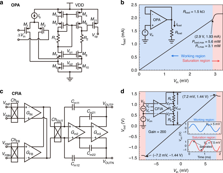
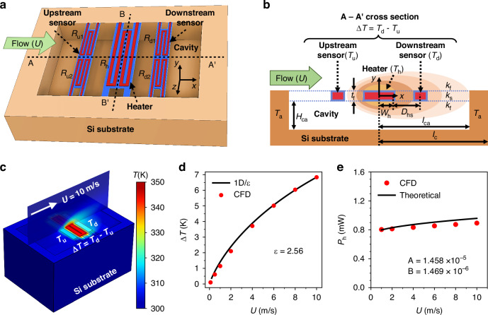
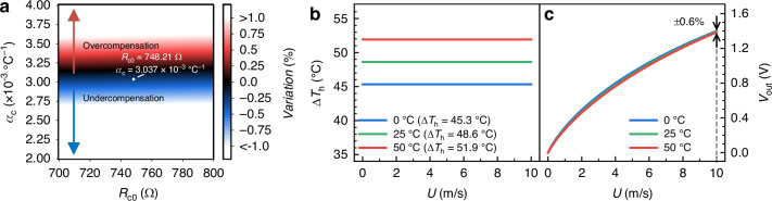
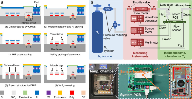
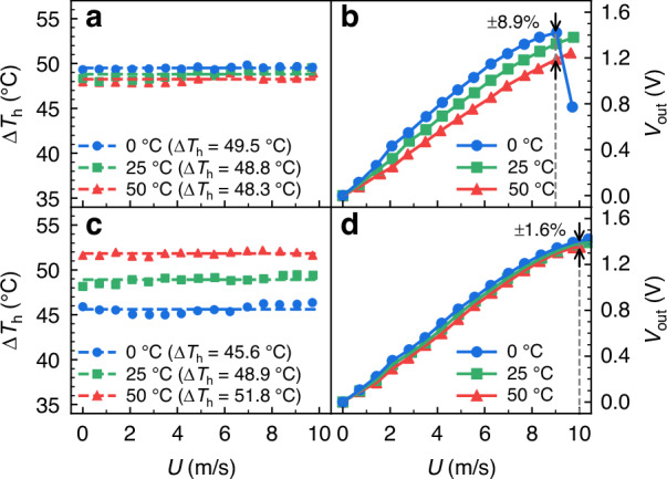
We present a system-level model with an on-chip temperature compensation technique for a CMOS-MEMS monolithic calorimetric flow sensing SoC. The model encompasses mechanical, thermal, and electrical domains to facilitate the co-design of a MEMS sensor and CMOS interface circuits on the EDA platform. The compensation strategy is implemented on-chip with a variable temperature difference heating circuit. Results show that the linear programming for the low-temperature drift in the SoC output is characterized by a compensation resistor Rc with a resistance value of 748.21 Ω and a temperature coefficient of resistance of 3.037 × 10⁻³ °C-1 at 25 °C. Experimental validation demonstrates that within an ambient temperature range of 0-50 °C and a flow range of 0-10 m/s, the temperature drift of the sensor is reduced to ±1.6%, as compared to ±8.9% observed in a counterpart with the constant temperature difference circuit. Therefore, this on-chip temperature-compensated CMOS-MEMS flow sensing SoC is promising for low-cost sensing applications such as respiratory monitoring and smart energy-efficient buildings.
© 2025. The Author(s).
Conflict of interest statement
Competing interests: The authors declare no competing interests.
Figures


Similar articles
-
A Temperature-Compensated Single-Crystal Silicon-on-Insulator (SOI) MEMS Oscillator with a CMOS Amplifier Chip.Micromachines (Basel). 2018 Oct 29;9(11):559. doi: 10.3390/mi9110559. Micromachines (Basel). 2018. PMID: 30715058 Free PMC article.
-
A High-Precision Bandgap Reference with Chopper Stabilization and V-Curve Compensation Technique.Micromachines (Basel). 2023 Dec 29;15(1):74. doi: 10.3390/mi15010074. Micromachines (Basel). 2023. PMID: 38258193 Free PMC article.
-
An Interface ASIC Design of MEMS Gyroscope with Analog Closed Loop Driving.Sensors (Basel). 2023 Feb 27;23(5):2615. doi: 10.3390/s23052615. Sensors (Basel). 2023. PMID: 36904819 Free PMC article.
-
Manufacture of a Polyaniline Nanofiber Ammonia Sensor Integrated with a Readout Circuit Using the CMOS-MEMS Technique.Sensors (Basel). 2009;9(2):869-80. doi: 10.3390/s90200869. Epub 2009 Feb 10. Sensors (Basel). 2009. PMID: 22399944 Free PMC article.
-
Microhotplates for Metal Oxide Semiconductor Gas Sensor Applications-Towards the CMOS-MEMS Monolithic Approach.Micromachines (Basel). 2018 Oct 29;9(11):557. doi: 10.3390/mi9110557. Micromachines (Basel). 2018. PMID: 30715056 Free PMC article. Review.
References
-
- Baldwin, A., Hudson, T. & Meng, E. A calorimetric flow sensor for ultra-low flow applications using electrochemical impedance. Proc. 2018 IEEE Micro Electro Mech. Syst. (MEMS) 361–364 (2018).
-
- Ejeian, F. et al. Design and applications of MEMS flow sensors: a review. Sens. Actuators, A295, 483–502 (2019).
-
- Mahalik, N. P. Principle and applications of MEMS: a review. Int. J. Manuf. Technol. Manag.13, 324–343 (2008).
-
- Khoshnoud, F. & de Silva, C. W. Recent advances in MEMS sensor technology–biomedical applications. IEEE Instrum. Meas. Mag.15, 8–14 (2012).
-
- Hartgenbusch, N., Borysov, M., Jedermann, R. & Lang, W. Reduction of power consumption and expansion of the measurement range by pulsed excitation of thermal flow sensors. Sens. Actuators A265, 313–320 (2017).
Grants and funding
- 52105582/National Natural Science Foundation of China (National Science Foundation of China)
- 2024A1515030026/Natural Science Foundation of Guangdong Province (Guangdong Natural Science Foundation)
- 2022A1515010894/Natural Science Foundation of Guangdong Province (Guangdong Natural Science Foundation)
- JCYJ20220818095810023/Shenzhen Science and Technology Innovation Commission