

High-Sensitivity Detection of Chiro-Optical Effects in Single Nanoparticles by Four-Wave Mixing Interferometry
- PMID: 39830856
- PMCID: PMC11741159
- DOI: 10.1021/acsphotonics.4c01782
High-Sensitivity Detection of Chiro-Optical Effects in Single Nanoparticles by Four-Wave Mixing Interferometry
Abstract
The field of chiral nanoparticles is rapidly expanding, yet measuring the chirality of single nano-objects remains a challenging endeavor. Here, we report a technique to detect chiro-optical effects in single plasmonic nanoparticles by means of phase-sensitive polarization-resolved four-wave mixing interferometric microscopy. Beyond conventional circular dichroism, the method is sensitive to the particle polarizability, in amplitude and phase. First, we demonstrate its application on single chiral nanohelices fabricated by focused ion beam induced deposition. We examined the combination of detected fields, which measures the particle polarizability, and showed that this is a sensitive reporter of chirality, providing dissymmetry factors (g α) impressively approaching unity. We then applied the method to a set of individual small gold nanoparticles near the dipole limit (60 nm nominal size), having correspondingly small chiral effects from the intrinsic lattice defects and nonperfectly spherical shape. We find that g α is randomly distributed in the population, consistent with its nondeterministic origin, but again exhibits remarkably high values, an order of magnitude higher than those obtained using conventional light absorption. Considering the importance of chiral plasmonic nanoparticles in fields ranging from catalysis to metamaterials, this technique offers a powerful way to quantify chiro-optical effects at the single particle level with unprecedented sensitivity.
© 2024 The Authors. Published by American Chemical Society.
Conflict of interest statement
The authors declare no competing financial interest.
Figures


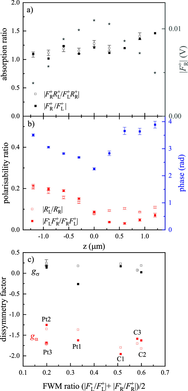
 ; absolute phase drifts between the measurements
are compensated in the ratio. Error bars are calculated as one standard
deviation, from the photon shot-noise and the laser fluctuations in
the experiment (see text). When not shown, errors are smaller than
the size of the symbols. (c) Dissymmetry factors gσ and gα for all
available helices (3 Pt and 3 C) measured at optimum focus versus
cross to copolarized FWM amplitude ratio (average of L and R). Symbols
relate the corresponding quantities used to calculate the dissymmetry
factor, as per legend in (a) and (b). The C and Pt helices shown in Figure 2 correspond to C2
and Pt3. Representative error bars are shown for Pt3.
; absolute phase drifts between the measurements
are compensated in the ratio. Error bars are calculated as one standard
deviation, from the photon shot-noise and the laser fluctuations in
the experiment (see text). When not shown, errors are smaller than
the size of the symbols. (c) Dissymmetry factors gσ and gα for all
available helices (3 Pt and 3 C) measured at optimum focus versus
cross to copolarized FWM amplitude ratio (average of L and R). Symbols
relate the corresponding quantities used to calculate the dissymmetry
factor, as per legend in (a) and (b). The C and Pt helices shown in Figure 2 correspond to C2
and Pt3. Representative error bars are shown for Pt3.


 versus phase of the cross to copolarized
FWM field ratio
versus phase of the cross to copolarized
FWM field ratio  , in single nominally spherical AuNPs of
60 nm diameter (same as in Figure 5). The red line shows the expected dependence assuming
a nonchiral quasi-spherical particle of ellipsoidal shape, with in-plane
orientation γ as sketched in the inset. (b) Dissymmetry factor gα versus the difference between the experimental
phase of
, in single nominally spherical AuNPs of
60 nm diameter (same as in Figure 5). The red line shows the expected dependence assuming
a nonchiral quasi-spherical particle of ellipsoidal shape, with in-plane
orientation γ as sketched in the inset. (b) Dissymmetry factor gα versus the difference between the experimental
phase of  and the phase expected from the ellipsoid
model. Blue symbols are the results for the nanohelices (using the
phase measured at the optimum focus z = 0, see Figure 3). The center cross
represents the ellipsoid model case.
and the phase expected from the ellipsoid
model. Blue symbols are the results for the nanohelices (using the
phase measured at the optimum focus z = 0, see Figure 3). The center cross
represents the ellipsoid model case.References
-
- Circular Dichroism: principles and Applications, 2 nd ed., Berova N.; Nakanishi K.; Woody R. W., Eds.; John Wiley and Sons, 2000.
LinkOut - more resources
Full Text Sources