

The biomechanical effect of the O-A angle on the aortic valve under left ventricular assist device support: a primary fluid-structure interaction study
- PMID: 39831250
- PMCID: PMC11740063
- DOI: 10.21037/jtd-24-1650
The biomechanical effect of the O-A angle on the aortic valve under left ventricular assist device support: a primary fluid-structure interaction study
Abstract
Background: Left ventricular assist device (LVAD) has been widely used as an alternative treatment for heart failure, however, aortic regurgitation is a common complication in patients with LVAD support. And the O-A angle (the angle between LVAD outflow graft and the aorta) is considered as a vital factor associated with the function of aortic valve. To date, the biomechanical effect of the O-A angle on the aortic valve remains largely unknown. The aim of this study was to evaluate the O-A angle how to influence the aortic valve biomechanical properties.
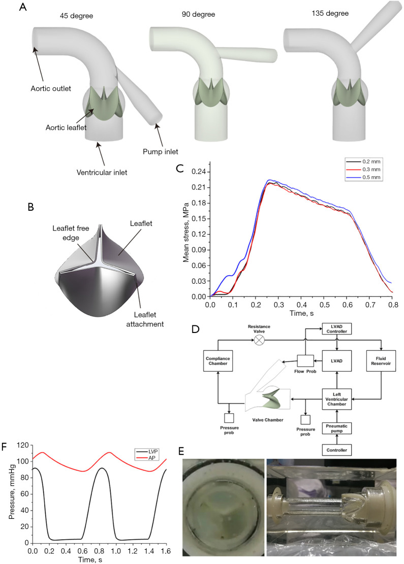
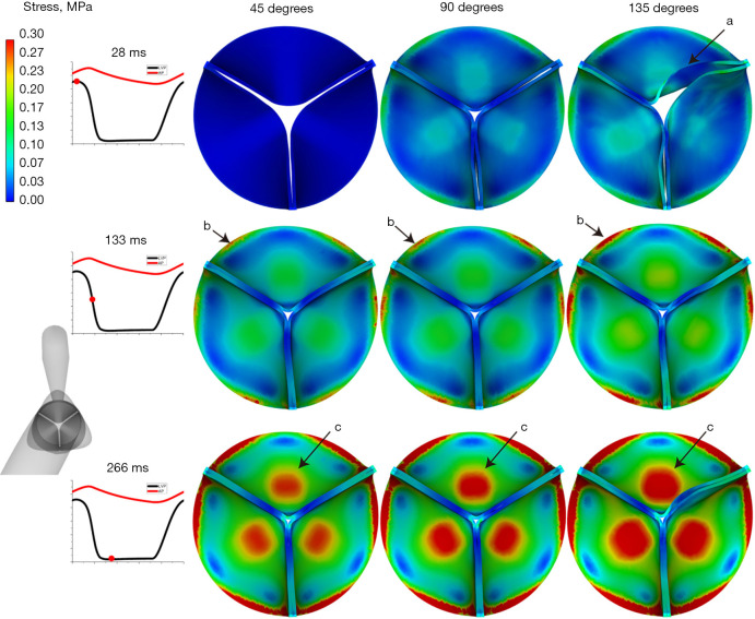
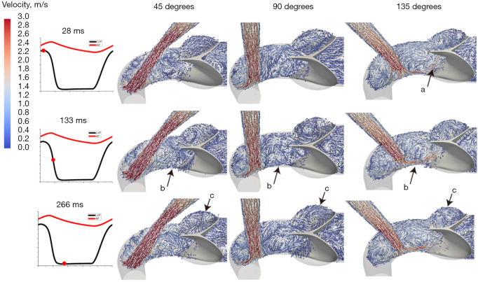
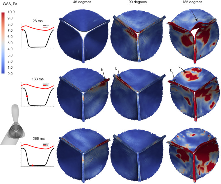
Methods: The current study employed a novel fluid-structure interaction (FSI) model that integrates the Lattice Boltzmann method (LBM) and the finite element method (FEM) to investigate the biomechanical effect of the O-A angle on the aortic valve under LVAD support. The biomechanical status of the aortic valve was evaluated at three different O-A angles (45, 90 and 135 degrees) and. four indicators, including stress distribution, the mean stress, the axial hemodynamic force (AHF) and the wall shear stress (WSS) distribution were evaluated at three timepoints (28, 133, and 266 ms).
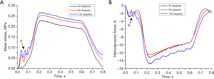
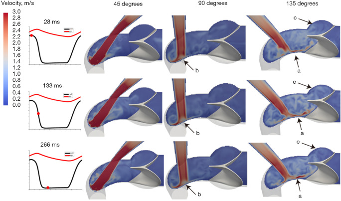
Results: The results showed that the stress and the high-stress region on the aortic leaflets increased as the O-A angle increased and as the difference between the left ventricular pressure (LVP) and aortic pressure (AP) increased. And the aortic insufficiency was observed at the 28 ms (systolic phase) in the 135-degree O-A angle. During the systolic phase, significant fluctuation in the mean stress was observed when the O-A angle was 90 or 135 degrees. During the diastolic phase, the mean stress increased in the three O-A angle conditions when the difference between the LVP and AP increased. Regarding to the AHF, an obvious fluctuation was observed during the systolic phase (0-100 ms) in the 135-degree O-A angle. During the diastolic phase, the AHF increased in the three O-A angle conditions when the difference between the LVP and AP increased. For the WSS distribution evaluation, the WSS was increased when the O-A angle increased. At 28 ms (the systolic phase), a high WSS was located on the free edge of the leaflets, and the deformed leaflets were observed in the 135-degree O-A angle. And at 133 ms (the rapid diastolic phase), a high WSS was observed at the free edge of the leaflets when the O-A angles were 45 or 90 degrees, and at both free edge and belly of the leaflets in the 135-degree O-A angle.
Conclusions: The O-A angle is closely associated with the biomechanical status of the aortic valve under LVAD support. A large O-A angle caused high stress and WSS on the aortic leaflets, as well as broad stress and WSS distribution, thus leading to deformed leaflets and retrograde flow. Therefore, optimization of the O-A angle will favor to maintain aortic valve function.
Keywords: Aortic valve; O-A angle; biomechanics; fluid-structure interaction (FSI); left ventricular assist device (LVAD).
2024 AME Publishing Company. All rights reserved.
Conflict of interest statement
Conflicts of Interest: All authors have completed the ICMJE uniform disclosure form (available at https://jtd.amegroups.com/article/view/10.21037/jtd-24-1650/coif). W.W. is from Jiangsu STMed Technology Co., Ltd., Suzhou, China. The other authors have no conflicts of interest to declare.
Figures
References
-
- Colombo PC, Ibeh C, Melmed KR, et al. Neurologic Complications: Pathophysiology, Incidence, Types, Prevention, and Management. In: Barac YD, Silvestry SC, Daneshmand MA, et al. editors. Textbook of Transplantation and Mechanical Support for End-Stage Heart and Lung Disease. Wiley 2023:945-65.
LinkOut - more resources
Full Text Sources
Research Materials