. 2025 Jan 24;11(4):eadr3654.
doi: 10.1126/sciadv.adr3654. Epub 2025 Jan 22.

Deployable electronics with enhanced fatigue resistance for crumpling and tension

Affiliations

Deployable electronics with enhanced fatigue resistance for crumpling and tension

Insic Hong et al. Sci Adv. .

Abstract

Highly packable and deployable electronics offer a variety of advantages in electronics and robotics by facilitating spatial efficiency. These electronics must endure extreme folding during packaging and tension to maintain a rigid structure in the deployment state. Here, we present foldable and robustly deployable electronics inspired by Plantago, characterized by their tolerance to folding and tension due to integration of tough veins within thin leaf. The primary design approach for these electronics involves a high resistance to folding and tension, achieved through a thin multilayered electronic composite, which manages the neutral axis and incorporates tough Kevlar. The fabricated electronics can be folded up to 750,000 times without malfunctions and endure pulling an object 6667 times heavier than itself without stretching. Such robust electronics can be used as a deployable robot with sensor arrays, demonstrating practical applicability, as it maintains their mechanical and electrical properties during inflation from the packaged state.


Figures

Fig. 1.
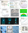
Fig. 1.. Trampling-tolerant leaf-inspired electronic composite.
(A) The deformation-tolerant electronic composite (DTEC) inspired by the leaf and vein structure of P. asiatica. (B) Exploded-view schematic illustration of DTEC (K-PDMS/flexible core-shell structure/K-PDMS). (C) Schematic illustration and graph for the comparison of the stress and strain curves of P. asiatica and inspired DTEC (yellow, vein and Kevlar; green, leaf and flexible electronics). (D) Photographs of the crumpled and stretched DTEC without damage to the electrode (serpentine pattern, electrode; straight pattern, Kevlar). (E) DTEC-based deployable gripper being cramped to a small volume without electrical malfunctioning and then gripping the objects while monitoring its physical properties in deployment. (F) Maximum strain applied on the PET layer and fatigue cycle when folded in half. (G) Tensile stress of PDMS and Kevlar composite at 2% strain.
Fig. 2.
Fig. 2.. Theoretical and experimental analyses of flexible core-shell structure for folding.
(A) Schematic illustration of the neutral-axis and strain engineering to fabricate the flexible core-shell structure. (B) Position of the neutral axis (X) in the flexible core-shell structure according to Young’s modulus and thickness of PDMS. (C) εx,PET in flexible core-shell structure depending on the thickness of PDMS. (D) Cross-sectional SEM images of completely folded flexible core-shell structure. (E) FEA modeling for the change in x-direction strain of the flexible core-shell structure when folded in half. (F) Sequential photograph of the large-sized flexible core-shell structure embedding LED circuit folded in half four times. (G) Hysteresis of the flexible core-shell structure for folding and unfolding. (H) Photographs and optical microscope images of the flexible core-shell structure and inner core electrode after crumpling. (I) Comparison of the resistance of the folded flexible core-shell structure and inner core electrode without PDMS.
Fig. 3.
Fig. 3.. Characterization and performance of DTEC for tension.
(A) Change in resistance of DTEC without Kevlar wire under tensile force increases (specimen width, 10 mm; length, 30 mm). (B) Uniaxial tensile tests of DTEC according to the gap between Kevlar wires. (C) FEA modeling of DTEC for tension. (D) Behavior for tearing in PDMS and DTEC. (E) Change in resistance and strain in DTEC according to the tensile force. (F) Photographs of the DTEC lifting a weight (10 kg). (G and H) Comparison of yield strength and fatigue life between the studied DTEC and results found in the references, plotted against foldability. Data are from references. Where the radius of curvature is not indicated in the paper, the radius of curvature when the normalized resistance (∆R/R0) is 0.1 was selected.
Fig. 4.
Fig. 4.. Classification of the different physical information of the deployable gripper.
(A) Photographs of the deployable gripper incorporating the temperature, pressure, and proximity sensors. (B) Sequential change in the resistance of the deployable gripper during each state. (C) Comparison of the electrode resistances of the crumpled DTEC and LDPE. (D) Comparison of the load capacity on the deployable grippers with and without Kevlar. (E) Comparison of pressure and mean stiffness in deployable grippers with and without Kevlar. (F) Approach detection of the deployable gripper through the proximity sensor. (G) Temperature mapping of the gripped hand using temperature sensors. (H) Pressure mapping for gripping a hand through the pressure sensors. (I) Sequential photographs and infrared images of the deployable gripper gripping the boiled egg and frozen strawberry. (J) Distance, temperature, and pressure of the egg and strawberry monitored with the deployable gripper.

Similar articles

References

    1. Fenci G. E., Currie N. G., Deployable structures classification: A review. Int. J. Space Struct. 32, 112–130 (2017).
    1. Song S., Fallegger F., Trouillet A., Kim K., Lacour S. P., Deployment of an electrocorticography system with a soft robotic actuator. Sci. Robot. 8, eadd1002 (2023). - PubMed
    1. Melancon D., Gorissen B., García-Mora C. J., Hoberman C., Bertoldi K., Multistable inflatable origami structures at the metre scale. Nature 592, 545–550 (2021). - PubMed
    1. Gao T., Bico J., Roman B., Pneumatic cells toward absolute Gaussian morphing. Science 381, 862–867 (2023). - PubMed
    1. Puig L., Barton A., Rando N., A review on large deployable structures for astrophysics missions. Acta Astronaut. 67, 12–26 (2010).

LinkOut - more resources