. 2025 Jan 7:11:1462717.
doi: 10.3389/frobt.2024.1462717. eCollection 2024.

Reliable and robust robotic handling of microplates via computer vision and touch feedback

Affiliations

Reliable and robust robotic handling of microplates via computer vision and touch feedback

Vincenzo Scamarcio et al. Front Robot AI. .

Abstract

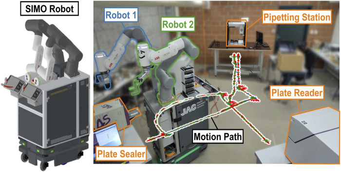
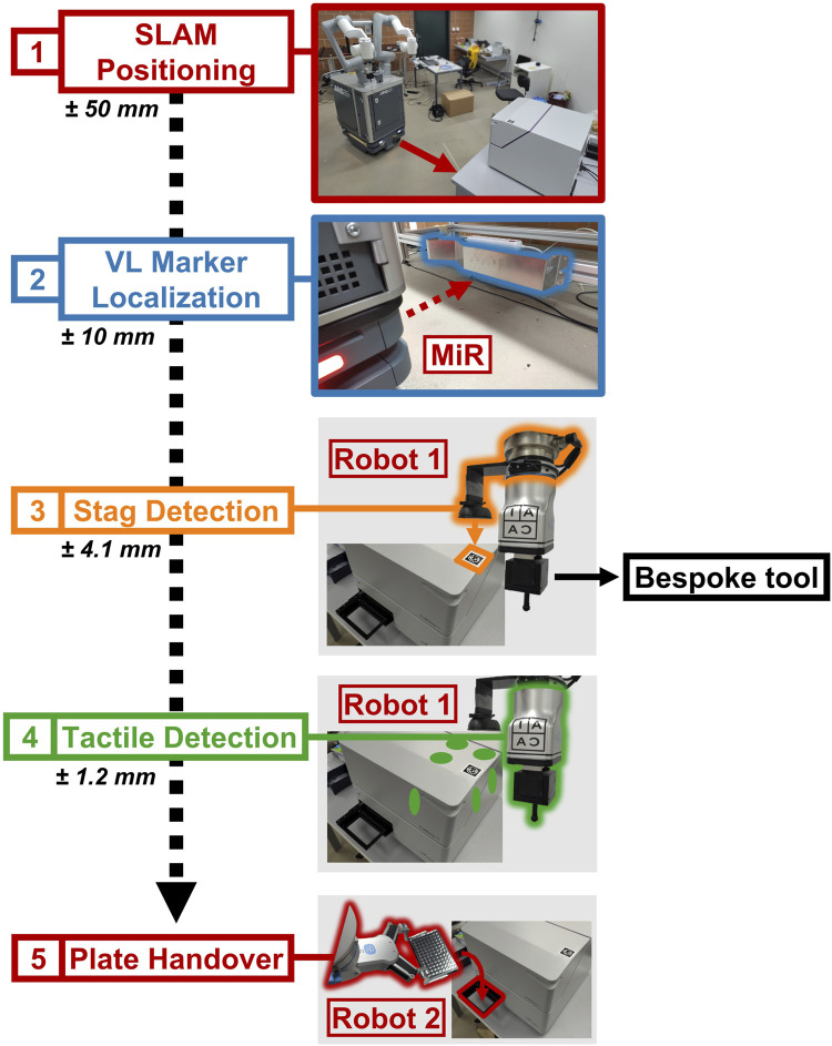
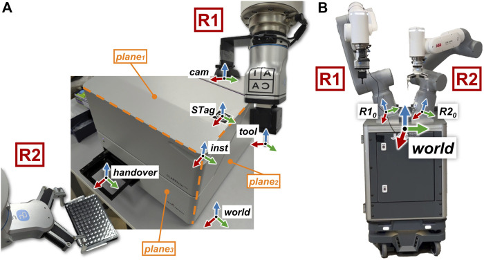
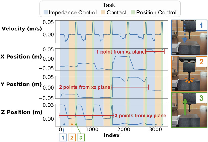
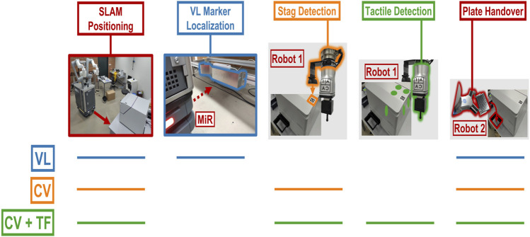
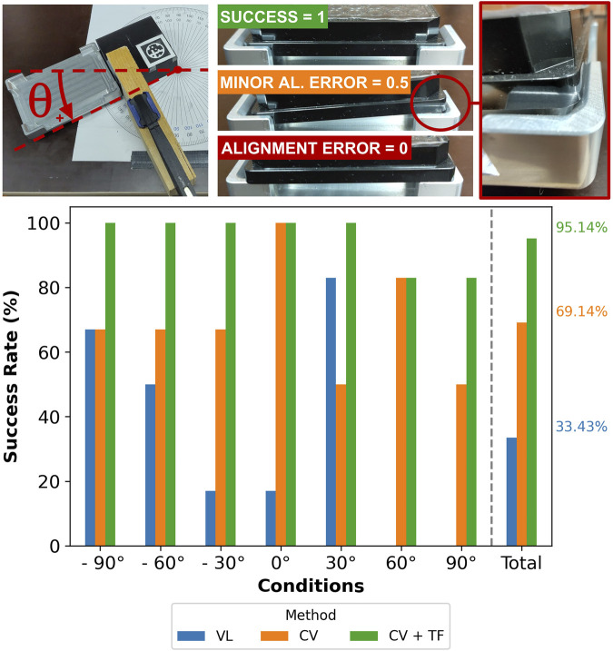
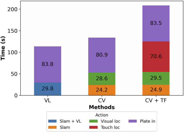
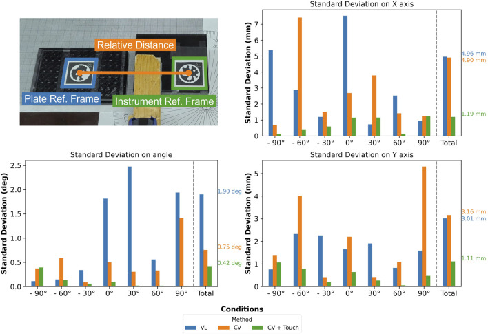
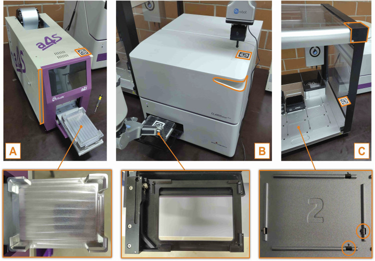
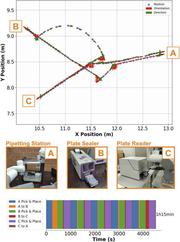
Laboratory automation requires reliable and precise handling of microplates, but existing robotic systems often struggle to achieve this, particularly when navigating around the dynamic and variable nature of laboratory environments. This work introduces a novel method integrating simultaneous localization and mapping (SLAM), computer vision, and tactile feedback for the precise and autonomous placement of microplates. Implemented on a bi-manual mobile robot, the method achieves fine-positioning accuracies of ± 1.2 mm and ± 0.4°. The approach was validated through experiments using both mockup and real laboratory instruments, demonstrating at least a 95% success rate across varied conditions and robust performance in a multi-stage protocol. Compared to existing methods, our framework effectively generalizes to different instruments without compromising efficiency. These findings highlight the potential for enhanced robotic manipulation in laboratory automation, paving the way for more reliable and reproducible experimental workflows.

Keywords: automation; computer vision; life science; mobile robotics; robot manipulation.


Conflict of interest statement

The authors declare that the research was conducted in the absence of any commercial or financial relationships that could be construed as a potential conflict of interest.

Figures

FIGURE 1
FIGURE 1
System setup used in this work, consisting of SIMO (left), a bi-manual mobile robot that mounts two robotic arms ( Robot1 and Robot2 ) on a mobile base, and three laboratory instruments (a pipetting station, a plate sealer, and a plate reader). The robot motion path between the three experimental stations is also shown.
FIGURE 2
FIGURE 2
Flow diagram detailing the robot–instrument interaction, highlighting the steps in sequence. SIMO uses SLAM to move to the waypoint, defined for every experimental station (1), and then it localizes the VL Marker, associated with the station (2). Robot1 uses computer vision to estimate the marker’s pose (3), and then it exploits impedance control and the specialized tool to touch the instrument on three faces (six-point touch feedback) (4). Robot2 can perform plate placement after it is informed by Robot1 about the instrument’s pose (5).
FIGURE 3
FIGURE 3
(A): illustration of the main reference frames involved in the robot–instrument interaction, highlighting the touch planes on the instrument. (B): the “world” reference frame is positioned centrally, in between and in front of robotic arms R1 and R2 . The RGB color model represents the axes, with each reference frame labeled accordingly. The labels R1 and R2 designate the two robotic arms.
FIGURE 4
FIGURE 4
Plots showing the velocity and the position of the tool tip as it executes the touch feedback routine for six points in three perpendicular planes. The plots have different colors depending on the task the robot is executing (impedance control going down, contact, and position control going up). The contact point is estimated by considering when the tool’s velocity is 0 while R1 is in impedance control mode.
FIGURE 5
FIGURE 5
Overview of the strategies to perform the plate pick-and-place task. The colored lines indicate the specific actions performed in each strategy: “VL,” “CV,” and “CV + TF.”
FIGURE 6
FIGURE 6
Overview of the hardware modules and their communication protocols; each node represents a module in the workflow. Interconnecting lines represented with different colors detail the communication protocols used between the various modules.
FIGURE 7
FIGURE 7
Map of the laboratory, generated by the MiR’s LiDAR, showing the positions of the three experimental stations: the plate sealer, plate reader, and pipetting station. The gray, double-colored squares represent recorded navigation points, while the robot’s current position is shown as a monocolored gray rectangle labeled “SIMO.” The red marks indicate real-time LiDAR data, with the black lines representing the room’s hardcoded layout. If the LiDAR data (red) does not align with the black lines—for example, showing red dots or lines in the room’s interior—this indicates that objects are obstructing the LiDAR sensor.
FIGURE 8
FIGURE 8
Assessment of the success rate for different methods (“VL,” “CV,” and “CV + TF”) and several angular displacements (ranging from 90° to +90° ) of the mockup instrument (mockup1) . The visual criteria to compute the success rate are also shown with photographs. The “CV + TF” method provides more consistent results among all conditions, followed by “CV” and “VL.” Every condition (defined by the angular displacement) was tested three times for each method.
FIGURE 9
FIGURE 9
Column plot showing the total execution time for three methods (“VL,” “CV,” and “CV + TF”). The single column is split into colored rectangles that identify different actions performed by the robot; the time to run single actions is enclosed in the corresponding rectangle. “VL” is the fastest method, followed by “CV” and “CV + TF.”
FIGURE 10
FIGURE 10
Assessment of the standard deviation (X, Y, and angular) of different methods (“VL,” “CV,” and “CV + TF”) for several angular displacements (ranging from 90° to +90° ) of the mockup instrument (mockup2) . The photograph on top details how the standard deviation is computed; the mockup instrument (in green) and the plate (in blue), respectively, have a fiducial marker that is used to compute their relative pose and its associated standard deviation.
FIGURE 11
FIGURE 11
Photographs that show the three real instruments used to test the “CV + TF” method. (A): Plate sealer, (B): Plate reader, (C): Pipetting station. The important implementation details are highlighted in orange, while the photographs in the second row show the instruments’ handover position.
FIGURE 12
FIGURE 12
Summary of the large-scale stress test. The upper plot shows the robot’s position in the room as it is executing one round of the CMC experiment; the orange letters highlight the positions of the three experimental stations on the map ((A): Plate sealer, (B): Plate reader, (C): Pipetting station). The photographs in the middle illustrate the robot–instrument interaction, while the single horizontal column plot in the lower part shows the total time to run the CMC protocol five times in a row ((A): Plate sealer, (B): Plate reader, (C): Pipetting station). Every color highlights the time to perform a specific task to complete the experiment.

Similar articles

References

    1. Abolhasani M., Kumacheva E. (2023). The rise of self-driving labs in chemical and materials sciences. Nat. Synth. 2, 483–492. 10.1038/s44160-022-00231-0 - DOI
    1. Ali M. M., Liu H., Stoll N., Thurow K. (2016). “Multiple lab ware manipulation in life science laboratories using mobile robots,” in 2016 17th international conference on mechatronics-mechatronika (ME), (Prague, Czech Republic: IEEE; ), 1–7.
    1. Baker M. (2016). Reproducibility crisis. Nature 533, 353–366. 10.1038/533452a - DOI - PubMed
    1. Benligiray B., Topal C., Akinlar C. (2019). Stag: a stable fiducial marker system. Image Vis. Comput. 89, 158–169. 10.1016/j.imavis.2019.06.007 - DOI
    1. Bostelman R., Hong T., Marvel J. (2016). Survey of research for performance measurement of mobile manipulators. J. Res. Natl. Inst. Stand. Technol. 121, 342. 10.6028/jres.121.015 - DOI - PMC - PubMed

LinkOut - more resources