Review
. 2025 Jun;12(24):e2410289.
doi: 10.1002/advs.202410289. Epub 2025 Jan 23.

Advances in Symbiotic Bioabsorbable Devices

Affiliations
Review

Advances in Symbiotic Bioabsorbable Devices

Chang Zhu et al. Adv Sci (Weinh). 2025 Jun.

Abstract

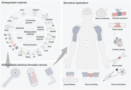
Symbiotic bioabsorbable devices are ideal for temporary treatment. This eliminates the boundaries between the device and organism and develops a symbiotic relationship by degrading nutrients that directly enter the cells, tissues, and body to avoid the hazards of device retention. Symbiotic bioresorbable electronics show great promise for sensing, diagnostics, therapy, and rehabilitation, as underpinned by innovations in materials, devices, and systems. This review focuses on recent advances in bioabsorbable devices. Innovation is focused on the material, device, and system levels. Significant advances in biomedical applications are reviewed, including integrated diagnostics, tissue repair, cardiac pacing, and neurostimulation. In addition to the material, device, and system issues, the challenges and trends in symbiotic bioresorbable electronics are discussed.

Keywords: biodegradable materials; biotherapeutics; symbiotic bioabsorbable devices.


Conflict of interest statement

The authors declare no conflict of interest.

Figures

Figure 1
Figure 1
Symbiotic bioabsorbable materials, devices, and biomedical applications.
Figure 2
Figure 2
Symbiotic bioabsorbable materials.
Figure 3
Figure 3
Schematic diagram of symbiotic bioabsorbable material degradation in vivo. a) The relationship between device function and mass loss. b) Degradation rate diagram of symbiotic bioabsorbable materials. c) Symbiotic bioabsorbable inorganic material degradation mechanism diagram. d) Symbiotic bioabsorbable polymer material degradation mechanism diagram.
Figure 4
Figure 4
Biodegradation mechanism of inorganic materials. a) Specific degradation reactions of bioabsorbable materials. b) Zn. Reproduced with permission from ref. [52] Copyright 2023, American Chemical Society. c) W, Mo, Fe. Reproduced with permission.[ 24 ] Copyright 2017, WILEY‐VCH Verlag GmbH & Co. KGaA, Weinheim. d) ZnO. Reproduced with permission.[ 27 ] Copyright 2019, WILEY‐VCH Verlag GmbH & Co. KGaA, Weinheim. e) MoS2, WS2. Reproduced with permission.[ 55 ] Copyright 2022, Wiley‐VCH GmbH. f) Si. Reproduced with permission from ref. [28] Copyright 2012, American Association for the Advancement of Science. g) Si. Reproduced with permission from ref. [58] Copyright 2017, American Chemical Society. h) PLGA in PBS at 37 °C. Reproduced with permission.[ 67 ] Copyright 2022, American Chemical Society. i) Polyanhydride films with 10% PEG. Reproduced with permission.[ 68 ] Copyright 2017, The American Association for the Advancement of Science.
Figure 5
Figure 5
Bioabsorbable sensors. a,b) Bioabsorbable physical sensor; c–e) Bioabsorbable chemical sensor. a) Schematic of PBPS in rats and photos of wireless assessment of motor function. Reproduced with permission.[ 70 ] Copyright 2024, Wiley‐VCH GmbH. b) Schematic diagram of a bioabsorbable pressure sensor composed of monocrystalline silicon and silica layers and images of intracranial temperature and pressure monitoring in rats. Reproduced with permission.[ 71 ] Copyright 2018, Springer Nature. c) Large‐area micropattern PEDOT: PSS process flow and specific device pictures. Reproduced with permission from ref. [32] Copyright 2016, Elsevier B.V. d) Schematic decomposition of transient silicon CMOS devices. Reproduced with permission.[ 72 ] Copyright 2015, American Chemical Society. e) Biodegradable neurotransmitter detection system and in vivo test diagram. Reproduced with permission.[ 73 ] Copyright 2018, WILEY‐VCH Verlag GmbH & Co. KGaA, Weinheim.
Figure 6
Figure 6
Bioabsorbable batteries. a) Structure and optical image of four series Mg‐Mo cells and dissolution behavior. Reproduced with permission.[ 87 ] Copyright 2014, WILEY‐VCH Verlag GmbH & Co. KGaA, Weinheim. b) Structure diagram and in vivo experiment of Mg‐I2 battery with two electrolytes. Reproduced with permission.[ 89 ] Copyright 2022, The Royal Society of Chemistry. c) Structure diagram and degradation behavior of degradable MoO3‐Mo battery. Reproduced with permission.[ 100 ] Copyright 2022, Wiley‐VCH GmbH. d) Structure diagram and degradation behavior of polymer electrolyte battery. Reproduced with permission.[ 101 ] Copyright 2017, American Chemical Society. e) Polypeptide organic radical cell and synthesis method. Reproduced with permission.[ 98 ] Copyright 2021, Springer Nature. f) Structure diagram and in vivo demonstration of MO‐DM cell with imitation mitochondria structure. Reproduced with permission.[ 103 ] Copyright 2023, Wiley‐VCH GmbH.
Figure 7
Figure 7
Bioabsorbable supercapacitors. a) Schematic diagram and degradation behavior of a capacitor composed of a biodegradable metal film electrode and NaCl/Agarose gel electrolyte. Reproduced with permission.[ 24 ] Copyright 2017, WILEY‐VCH Verlag GmbH & Co. KGaA, Weinheim. b) Schematic diagram of the manufacturing process and application of supercapacitors based on SrMA/A‐rGO hydrogel electrodes. Reproduced with permission.[ 106 ] Copyright 2023, Wiley‐VCH GmbH. c) Structure, preparation process diagram, and implantation demonstration of biodegradable supercapacitor. Reproduced with permission.[ 107 ] Copyright 2019, WILEY‐VCH Verlag GmbH & Co. KGaA, Weinheim. d) Diagram of Mo‐MoOx electrode sheet and Alg‐Na gel electrolyte supercapacitor. Reproduced with permission.[ 110 ] Copyright 2021, The American Association for the Advancement of Science. e) Schematic diagram and in vivo experimental demonstration of Zn‐MoS2 supercapacitor. Reproduced with permission.[ 111 ] Copyright 2023, The American Association for the Advancement of Science. f) Schematic diagram of the manufacturing process of an edible Zn‐ion‐based MSC. Reproduced with permission.[ 115 ] Copyright 2022, American Chemical Society.
Figure 8
Figure 8
Bioabsorbable friction nanogenerator. a) Common bioabsorbable material sources, BN‐TENG device structure diagram, and in vivo experiment diagram. Reproduced with permission.[ 125 ] Copyright 2018, WILEY‐VCH Verlag GmbH & Co. KGaA, Weinheim. b) Schematic diagram, synthesis method of DBD‐TENG, and its application in respiratory signal monitoring. Reproduced with permission.[ 126 ] Copyright 2024, Wiley‐VCH GmbH. c) Preparation process, design principle, and application in monitoring physiological signals of BS‐TENGs of PEGDA/Lap hydrogel. Reproduced with permission.[ 129 ] Copyright 2023, American Chemical Society. d) Schematic diagram of BD‐TENG prepared by PLGA, PHB/V, PCL, and PVA and demonstration of nerve stimulation. Reproduced with permission.[ 124 ] Copyright 2016, The American Association for the Advancement of Science.
Figure 9
Figure 9
Bioabsorbable piezoelectric materials. a) Structure diagram and in vivo experimental demonstration of b‐WPUE. Reproduced with permission.[ 131 ] Copyright 2024, The American Association for the Advancement of Science. b) Structure diagram and microscopic characterization of flexible amino acid nanofibers. Reproduced with permission.[ 132 ] Copyright 2023, The American Association for the Advancement of Science. c) Synthesis method of γ‐glycine‐PEO piezoelectric materials and schematic diagram of different interface‐induced orientations. Reproduced with permission.[ 133 ] Copyright 2023, Elsevier Ltd. d) Schematic diagram of ferroelectric molecule crystal structure, specific properties and in vivo experimental demonstration. Reproduced with permission.[ 134 ] Copyright 2024, The American Association for the Advancement of Science.
Figure 10
Figure 10
Symbiotic bioabsorbable transistors. a) Structure diagram and degradation behavior of transient silicon‐based N‐channel transistor array. Reproduced with permission.[ 137 ] Copyright 2018, WILEY‐VCH Verlag GmbH & Co. KGaA, Weinheim. b) Schematic diagram of OECT array structure and demonstration as brain‐computer interface. Reproduced with permission.[ 138 ] Copyright 2023, Wiley‐VCH GmbH.
Figure 11
Figure 11
Symbiotic bioabsorbable diode. a) Schematic diagram of device structure and degradation behavior. Reproduced with permission.[ 28 ] Copyright 2012, The American Association for the Advancement of Science. b) Structure diagram and dissolution kinetics of transient diode. Reproduced with permission.[ 121 ] Copyright 2013, WILEY‐VCH Verlag GmbH & Co. KGaA, Weinheim. c) Photoelectric effect and principle of thin‐film silicon diode. Reproduced with permission.[ 139 ] Copyright 2022, Springer Nature.
Figure 12
Figure 12
Application of symbiotic bioabsorbable devices.
Figure 13
Figure 13
Brain monitoring. a) Schematic decomposition of neural electrode array structure and optical microscopic image. Reproduced with permission.[ 30 ] Copyright 2016, Springer Nature Limited. b) Schematic diagram and in vivo experimental demonstration of biodegradable pressure sensor. Reproduced with permission.[ 13 ] Copyright 2016, Springer Nature. c) Hydrogel diagram for wireless intracranial physiological sensor and in vivo experiment demonstration. Reproduced with permission.[ 140 ] Copyright 2024, Springer Nature. d) Electronic sensor array of deep brain neurochemicals and schematic diagram of in vivo experiment. Reproduced with permission.[ 55 ] Copyright 2022, Wiley‐VCH GmbH.
Figure 14
Figure 14
Vascular pressure and blood monitoring. a) MEA diagram and performance characterization for multi‐mode photoelectric heart monitoring. Reproduced with permission.[ 141 ] Copyright 2023, The American Association for the Advancement of Science. b) Schematic diagram of double coil structure and vessel wrapping for wireless data transmission. Reproduced with permission.[ 17 ] Copyright 2019, The Author(s), under exclusive licence to Springer Nature Limited. c) Structure and animal experimental demonstration of implantable bioabsorbable self‐powered sensor with triboelectric effect. Reproduced with permission.[ 142 ] 2021 Wiley‐VCH GmbH.
Figure 15
Figure 15
Nerve repair. a) Schematic illustration and explanation of the behavior of catheter‐like biodegradable and self‐powered neural repair devices. Reproduced with permission.[ 143 ] Copyright 2020, The American Association for the Advancement of Science. b) Schematic diagram of ACT‐TENG with sleeve band and demonstration of nerve repair. Reproduced with permission.[ 53 ] Copyright 2023, Springer Nature. c) Structure diagram of electrical stimulation device and effect of sciatic nerve implantation and repair. Reproduced with permission.[ 144 ] Copyright 2018, Springer Nature America. d) Electrical stimulation device structure diagram and repair effect diagram of neural repair device. Reproduced with permission.[ 146 ] Copyright 2020, Springer Nature. e) Schematic of the structure of RCDDS and the drug release process. Reproduced with permission.[ 147 ] Copyright 2023, Royal Society of Chemistry. f) Schematic diagram and synthesis process of biodegradable 3D piezoelectric scaffolds promoting spinal cord injury repair by electrical stimulation. Reproduced with permission.[ 38 ] Copyright 2022, American Chemical Society.
Figure 16
Figure 16
Bone repair. a) Schematic illustration of a silicon‐based 3D photoelectric scaffold in skull repair. Reproduced with permission.[ 148 ] Copyright 2023, The American Association for the Advancement of Science. b) Structure diagram of piezoelectric PLLA scaffold and demonstration of bone repair effect. Reproduced with permission.[ 149 ] Copyright 2022, The American Association for the Advancement of Science. c) Schematic diagram of PCM‐PLLA piezoelectric scaffold and experimental demonstration in vivo. Reproduced with permission.[ 150 ] Copyright 2024, Science China Press. Published by Elsevier B.V. and Science China Press. All rights are reserved, including those for text and data mining, AI training, and similar technologies. d) Hydrogel bone repair diagram and animal bone repair effect diagram. Reproduced with permission.[ 151 ] Copyright 2023, Springer Nature.
Figure 17
Figure 17
Wound Healing. a) Structure and degradation behavior of electrotherapy system for wound healing with electrical stimulation. Reproduced with permission.[ 152 ] Copyright 2023, The American Association for the Advancement of Science. b) Structural diagram and in vivo experimental image of double electrostimulation electronic bandage. Reproduced with permission.[ 153 ] Copyright 2024, Springer Nature. c) Structural diagram of HA‐PEG hydrogel and experimental demonstration of wound. Reproduced with permission.[ 154 ] Copyright 2023, The American Association for the Advancement of Science.
Figure 18
Figure 18
Cardiac pacing. a) Structure diagram and animal experimental image of bioabsorbable cardiac pacemaker lead. Reproduced with permission.[ 155 ] 2021 Wiley‐VCH GmbH. b) Schematic diagram of monolithic silicon heart pacing with spatiotemporal light stimulation and experimental demonstration in animals. Reproduced with permission.[ 156 ] Copyright, 2024 Springer Nature. c) Wireless bioabsorbable pacemaker structure and animal experimental images. Reproduced with permission.[ 15 ] Copyright, 2021 Springer Nature. d) Schematic diagram and demonstration of transient closed‐loop system for temporary cardiac pacing. Reproduced with permission.[ 157 ] Copyright 2022, The American Association for the Advancement of Science.
Figure 19
Figure 19
Neuromodulation. a) Optical image of biodegradable flexible photostimulated neural interface and schematic diagram of in vivo experiment. Reproduced with permission.[ 158 ] Copyright, 2024 Springer Nature. b) Schematic diagram of p+n and n+p si membranes photostimulating and inhibiting peripheral nerve activity in vivo. Reproduced with permission.[ 139 ] Copyright, 2022 Springer Nature. c) Photoelectric chemistry diagram of nano‐porous/non‐porous silicon materials and in vivo experimental demonstration. Reproduced with permission.[ 159 ] Copyright, 2022 Springer Nature.
Figure 20
Figure 20
Drug release. a) BEP material design structure, drug diagram, and craniotomy image. Reproduced with permission.[ 161 ] Copyright 2019, Springer Nature. b) Schematic diagram of HMPI controlled drug release design and application. Reproduced with permission.[ 162 ] Copyright 2023, Wiley‐VCH GmbH. c) ADDS structure diagram and application demonstration. Reproduced with permission.[ 163 ] Copyright 2023, Wiley‐VCH GmbH.
Figure 21
Figure 21
Future development roadmap of symbiotic bioabsorbable devices.

References

    1. Cingolani E., Goldhaber J. I., Marban E., Nat. Rev. Cardiol. 2018, 15, 139. - PMC - PubMed
    1. Lacour S. P., Courtine G., Guck J., Nat. Rev. Mater. 2016, 1, 16063.
    1. Navarro M., Michiardi A., Castano O., Planell J. A., J. R. Soc., Interface 2008, 5, 1137. - PMC - PubMed
    1. Ryu H., Seo M.‐H., Rogers J. A., Adv. Healthcare Mater. 2021, 10, 2002236. - PubMed
    1. Joung Y.‐H., Int. Neurourol. J. 2013, 17, 98. - PMC - PubMed

Substances

LinkOut - more resources